For newer systems (without polyimide M2 rods) it is not necessary to remove the pre-mounted MCP rear plate from the anode
for mounting of the MCP now:
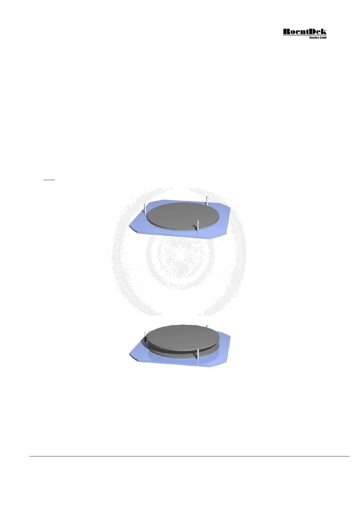
1. Place the rear plate with the indention for the MCP pointing upward according to the sketch below. Screw the three M3
guide rods symmetrically into three of the six M3 tapped holes. Remove the MCP carefully from their transport package
and insert the first one (the designated rear MCP in the stack) centered into the indention, with the bias angle marker
(triangle on the outer rim on one side) pointing upward. For MCP general handling see also instructions in the Appendix
of this manual. Touch MCPs only with care along the rim, preferably with gloves.
Unless otherwise noted, any of the supplied MCP can be selected for the position in the stack. The second (and possibly
a third) MCP will be placed with its mark also pointing upwards and should be rotated by about 180 azimuthal degrees
with respect to the mark position on the MCP under it. In a side view cross section of the stack, the pores of the MCP
would resemble a (broad) “v” shape (or chevron), or a “z” shape for triple stacking. Such an angle orientation is very
important for proper stack performance, however, any relative azimuthal angle between 150° and 210° will serve as well
as having exactly 180° between marks.
Optionally, shim rings can be supplied for being placed between MCP which may improve overall gain homogeneity and
(for HEX120) shall reduce the active MCP diameter to 100mm (which is beneficial for some multi-hit applications).
Usually, the delivered MCPs will be matched in resistance within 10% for direct stacking. If not, a shim ring with contact lug
must be used with cable connection to a feedthrough for bias via a high voltage supply. Please contact
RoentDek in
such a case
Figure 1.21: Rear metal plate with one MCP (DLD120 and HEX120)
After stacking the second (and possibly third) MCP carefully onto the first (with the bias angle marker pointing upwards
and rotated with respect to the lower MCP’s mark by about 180°) make sure that the MCPs are well-aligned with each
other and are centered in the indention, adjustments can be done by carefully moving the individual MCPs on the ring.
It is especially important to avoid that dust particles settle between the MCP during assembly.
Dust particles that may have settled can usually be blown away be spraying dry air across the MCP surface.
Figure 1.22: Assembly of MCP-stage 2 (DLD120 and HEX120)
If the MCPs need replacement mount a set with matching electrical resistance only or employ a shim ring with contact lug
for intermediate bias (see above).
2. Place the front metal ring with the indented side facing downward on the MCP. The guide pins will help in the alignment.
It is very important that the MCP stack is well centered and will fit into the indention of the front ring.
MCP Delay Line Detector Manual (11.0.1304.1) Page 19 of 83