Figure 1.23: Assembly of MCP-stack - Stage 3-1 (DLD120 and HEX120)
Now fix the stack with three plastic screws very carefully and only lightly. Due to the indentions in the rear plate and the front
ring, the MCP will not fall out even if the screws are not entirely tight. Remove the guide pins and add the other three screws.
Once all screws are in place fix them again slightly without excessive force
Figure 1.24: Assembly of MCP-stack - Stage 3-2 (DLD120 and HEX120)
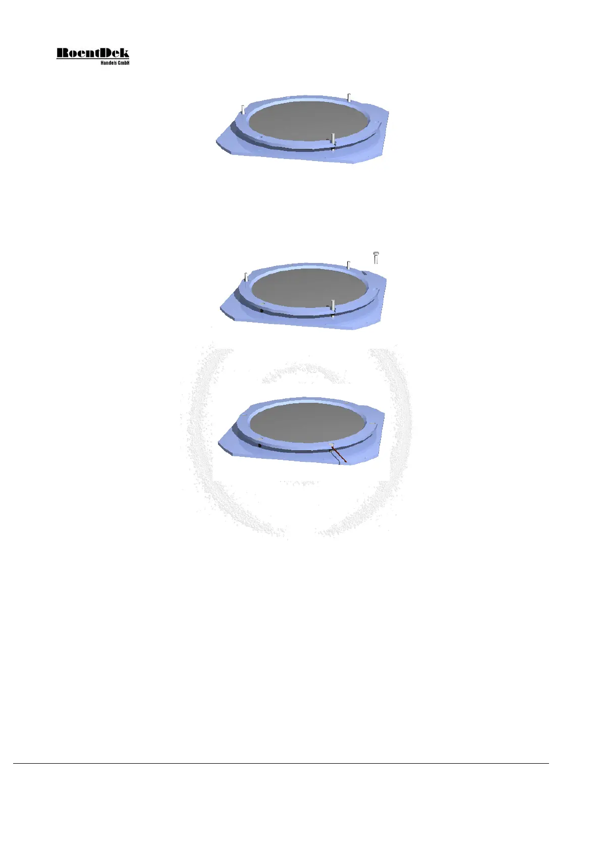
Figure 1.25: Assembly of MCP-stack - Stage 3-3 (DLD120 and HEX120)
3. Now the MCP back contact cable can be fixed to the rear metal plate on any of the M2 threads along the edges.
The MCP front contact cable can be fixed to the front ring likewise on a M2 threaded hole or as in Figure 1.25. For this
remove the screw from the whole with the gap for the cable, insert the MCP front contact cable and re-fix the screw as
tight as the others.
On older systems, the mounted MCP stack now has to be fixed to the anode via Vespel M2 rods in the corners of the
delay-line anode using nuts on either side of the corresponding mounting holes in the rear plate (or the wing rails in case
of HEX120). It is only necessary to sink the M2 polyimide rods by 3-4mm into the anode body, so that they are safely
fixed.
Page 20 of 83 MCP Delay Line Detector Manual (11.0.1304.1)