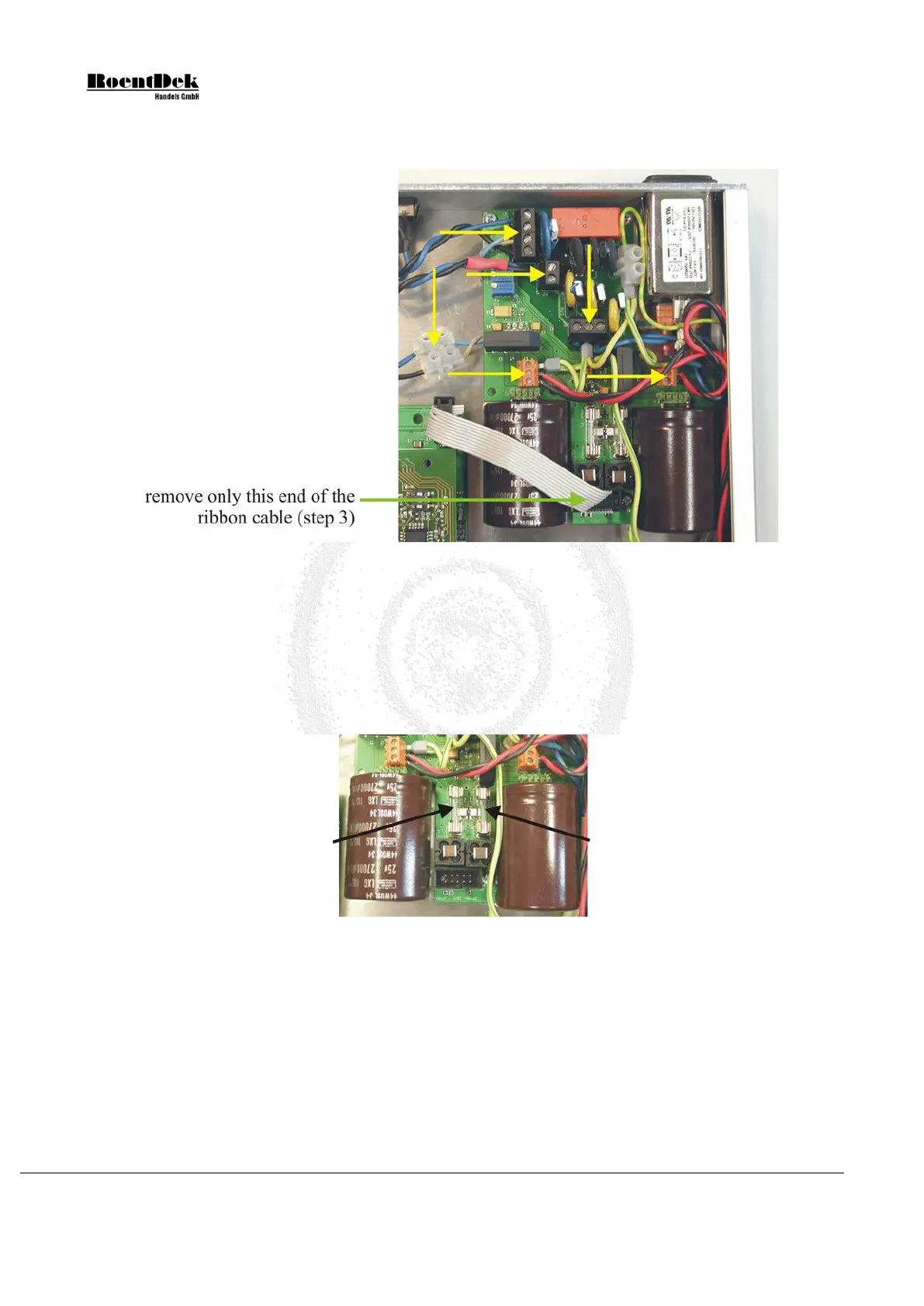
2) Remove the power cord and all other cables connected to the ATR19. Open the ATR19 case. Check that all internal
cables are correctly fixed in the terminals (yellow arrows in the picture below).
Figure 3.21: Remove the ribbon cable from the power supply
3) Remove the ribbon cable from the power supply (green arrow in the picture above). Make sure not to remove the
other end of the ribbon cable. This will ensure that you will not invert polarity when reconnecting the cable later.
4) Check the output fuses (see picture below). If broken replace with fuses of the following readings:
F1: 250V 1.6AF
F2: 250V 2.5AF
(F = (German:) flink = fast acting)
Figure 3.22: Output fuses
Use an ohmmeter to check that there are no short circuits between +V
out
and GND resp. -V
out
and GND (see picture below).
Page 50 of 83 MCP Delay Line Detector Manual (11.0.1304.1)