d
i
= ½ v
i
* ∆t
Equation 1.4
d
i
must be precisely known to make the images obtained via different layer combination coherent. o is an offset value that shall
unify the “time difference zero” of all three layers, i.e. it must be chosen so that geometrically the position lines for calculated
u, v, w have a common crossing point, e.g. w must be zero when u and v are zero.
For the HEX80 the single pitch delay is about 1.4ns. The exact values u, v, w, o differs from anode to anode. There relative
values must be precisely determined which can be done by a self-calibration routine (for details please contact
RoentDek).
o is also a function of connection cable lengths and cable lengths all the way to the TDC/TAC inputs (and internal offsets
therein) and must therefore be recalibrated whenever these parameters have changed. The single pitch delay for the HEX120
is about 1.75ns which corresponds to a pitch of 1mm or 1.5mm, depending on the anode version which you have received
(default: 1.5mm).
For detectors with central hole, the gaps in the wiring have to be taken into account. Please contact
RoentDek for the
program codes appropriate for your detector.
The linearity deviations in each delay-line layer should be calibrated to achieve optimal results. Please contact RoentDek for an
auto-linearization routine and advanced position codes.
The X and Y positions can be calculated from any combination of the Equation 1.2. If for a given event more signals than from
the minimum of two layers are available, it is recommended to choose signals from those two layers where the positions are
most distant from the respective delay line ends (or gaps).
In order to determine the time difference between an outer time marker and the particle impact, the signal at the MCP contact
can be used. But it is also possible to deduce the particle impact time from the delay-line signals:
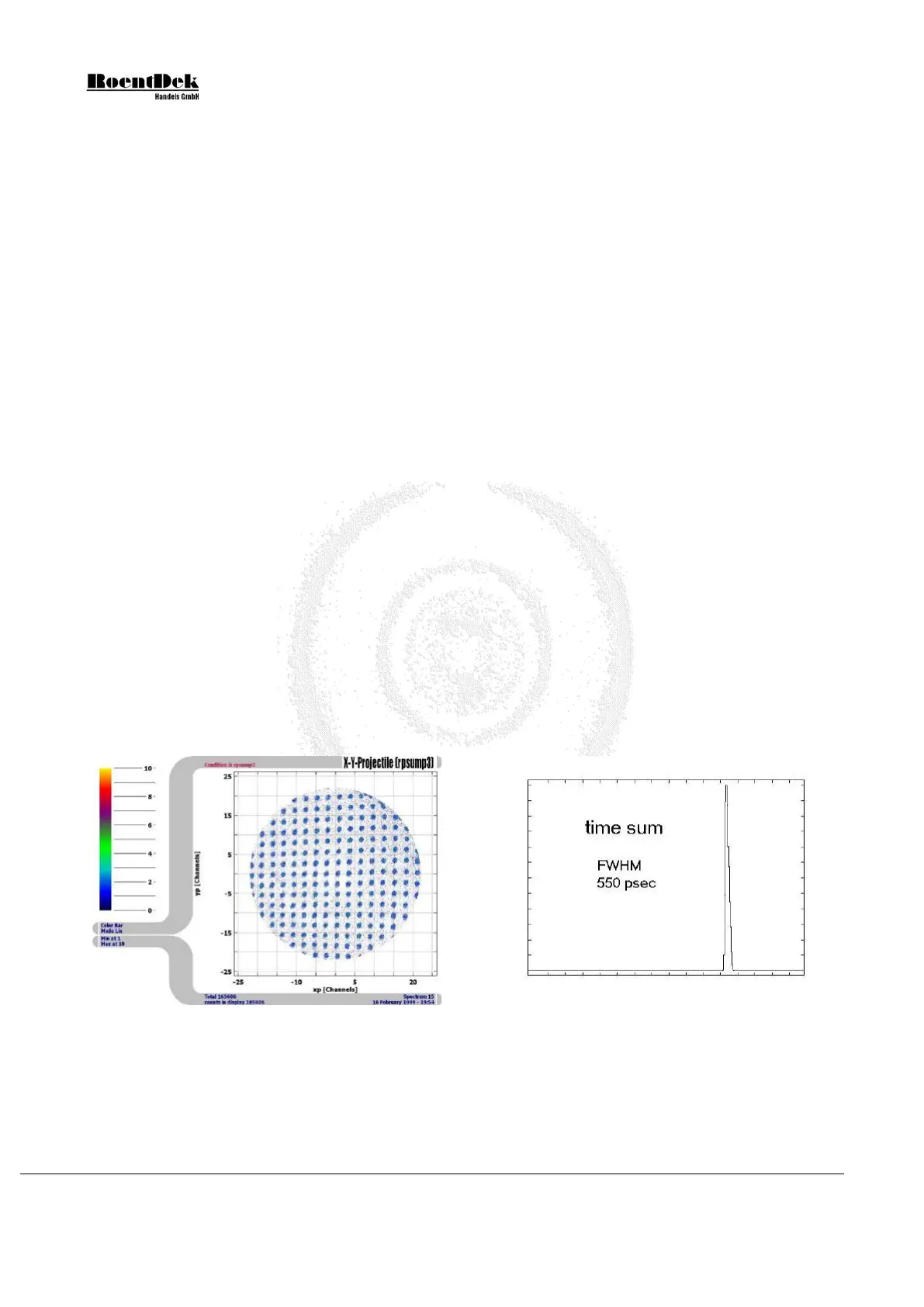
If the MCP signal is used as the time-zero, the “time sum” values
sumy = y1 + y2
sumz = z1 + z2 (only available for Hexanodes)
Equation 1.5
are constant within the time resolution (less than one ns) but have a slight “position walk” which can be determined by plotting
sum vs. difference (i.e. position). Thus it is also possible to deduce the particle impact time from these time sum values alone.
Even if the particle timing is not of interest, the time sum measurement can be used to verify a proper detector function.
Figure 1.2: Typical imaging/timing performance of a DLD40 detector. The detector (shaded by a mask) was
irradiated with
-particles. Similar or better results can be achieved with adequate read-out electronics. Temporal
resolution is significantly better than the
local time sum width (see right picture) which indicates an upper limit.
Page 10 of 83 MCP Delay Line Detector Manual (11.0.1304.1)