The Front-end timing electronics modules: Amplifier & CFD Module
RoentDek offers different versions of front-end timing electronics.
This manual contains the ATR19 description. If you have received different front-end electronics please refer to separate
manual(s) which shall replace the following section
This is (Version 11.0.1303.1). Please look for updates of this manual at
http://roentdek.com/manuals/
The readout of the MCP and delay-line anode signals requires amplifying and precise timing (discrimination) circuits such as
“Constant-Fraction Discriminators” (CFD). Those produce digital signals (like NIM or ECL) for a follow-up time measuring
device, e.g. a time-to-digital converter (TDC).
The ATR19 module was especially designed for this timing detector read out purpose. In the version as 1 HU 19” case with
internal mains power supply it can host up to four DLATR differential timing amplifier & CFD boards, each with two
independent channels. It provides all input/output connectors, level controls and a 100-125V/200-250V AC power adapter.
The module is typically delivered either with 3 boards (ATR19-6, 6 channels total), for use with the DLD detectors or with all
slots occupied (ATR19-8, 8 channels total) e.g. for use with Hex-detectors
*
. Each version can either provide the timing signals
as NIM or differential ECL level, e.g. depending on the requirements of the time measuring device.
The ATR19-2b module version as 4 HU cassette hosts only one card and contains the same input/output options as the larger
unit and comes with an external mains adapter. The older ATR19-2 model requires a mains power adapter with ±6V (<0.5A)
for operation, such as SPS1(b). Its circuits are similar to the internal supply in the ATR19-6/8 and can also be used as a back-
up external mains adapter for those units, and also for earlier (N)DLATR6/8 models, see Chapter 3.8.
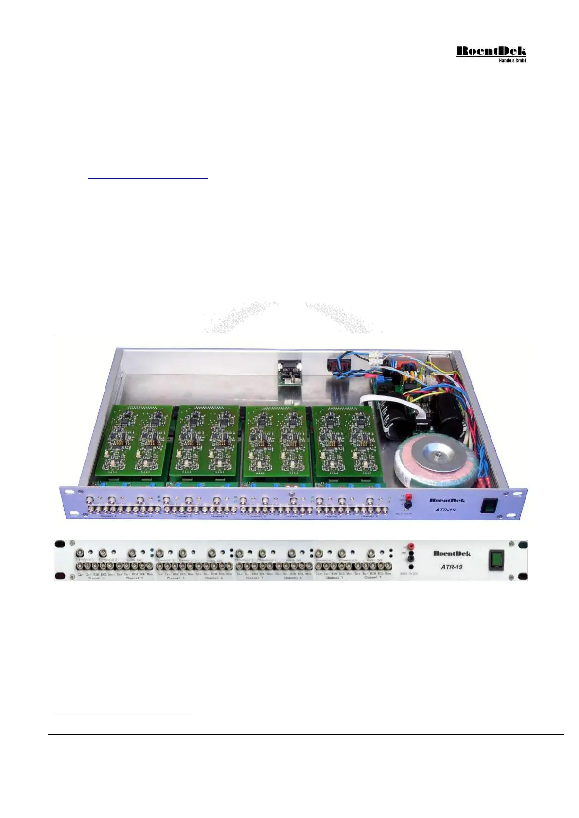
Figure 3.1: The ATR19 module
The differential amplifying stage of the internal DLATR-board has 200MHz band width with 100Ω input impedance, DC
coupled. However, the ATR19 in the standard version contains capacitors for AC-coupling of the inputs.
The ATR19 is usually operated as a non-symmetric (single input) amplifier with 50Ω impedance to ground, inverting (-) or
non-inverting (+). This non-symmetric operation is the default mode for the use of a delay-line detector in combination with
the (standard) FT4/12/16TP feedthrough and decoupling plugs.
The outputs of the ATR19 allow verification of the signals after the first amplification stage on the DLATR board (“analog”
signal) and of the NIM or ECL timing output signals. Amplification, trigger threshold and timing signal width can be adjusted
by potentiometers (default) or externally by DC levels (0 to +5V), the CFD “walk” adjust is automated (push-button) or pre-
*
However, a FAMP8+CFD8 type combination is recommended with the Hexanode for improved multi-hit performance.
MCP Delay Line Detector Manual (11.0.1304.1) Page 35 of 83