3.8 The SPS1(b) mains adapter
The RoentDek SPS1/SPS1b are external power supplies for the RoentDek (N)DLATR8, (N)DLATR6 and ATR19
units. The SPS1b can also supply the CFD1b.
The SPS1 provides DC-outputs (V
out
) adjustable between 5V and 6V, both positive and negative from 100-125V/200-250V,
50/60Hz AC mains power. The SPS1b provides ±6V and additionally -5.2V on a separate line. A switch on the back panel is
used to select the mains power range. V
out
can be adjusted between 5V and 6V. The output voltages are supplied via a 9-pin
Sub-D connector which is compatible with the external power input sockets of the
RoentDek (N)DLATR8, (N)DLATR6,
ATR19 (and CFD1b) units.
The RoentDek SPS1 is ready for use. To prevent any damage or injuries, please read the following sections before. The
RoentDek SPS1 power supply works with hazardous mains voltage. Always make sure to:
• keep the SPS1 power supply dry (use indoors only)!
• never insert any objects into the ventilation openings of the SPS1 power supply!
• never block the ventilation openings on the top and bottom of the case!
• only operate the SPS1 power supply while the case is closed!
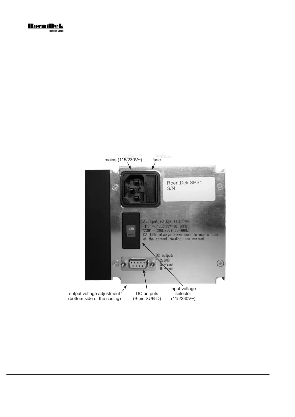
Figure 3.16 shows the connectors on the rear panel of the SPS1 power supply. The power switch is located on the front panel.
Figure 3.16: Connectors on the back of the SPS1.
The SPS1b features two identical output connectors which additionally provide -5.2V on pin 3.
: Before connecting or disconnecting any cables always make sure that the power switch on the front
panel is in its ‘off’ position (digit ‘0’ can be seen).
a) Make sure that the correct AC input voltage range is set:
‘115’ for operation with 100-125V AC 50-60Hz
‘230’ for operation with 200-250V AC 50-60Hz
If the wrong range is set, see chapters 3.8.2 for changing the supply voltage range and the input fuse.
Page 46 of 83 MCP Delay Line Detector Manual (11.0.1304.1)