5.4 HVT and HVT4 High Voltage Terminators
If the micro-channel plate stack shall be biased with the same polarity on both sides (e.g. positive, for electron detection), most
high voltage power supplies’ control circuits cannot stabilize the low bias setting: as one supply is ramped to a higher bias, e.g.
on MCP back side, it will “pull away” the bias of the other MCP side in spite of a low-voltage setting on the dial. This is due to
the coupling of the supplies via the MCP stack resistance R
MCP
. On the RoentDek HV2/4 and similar units the effect can
directly be observed on the voltage display (when the set voltage is zero or low enough).
This can be avoided by “terminating” the low-bias output to “ground” via a well-selected resistor R
HVT
, e.g. of 1MΩ. For this
purpose
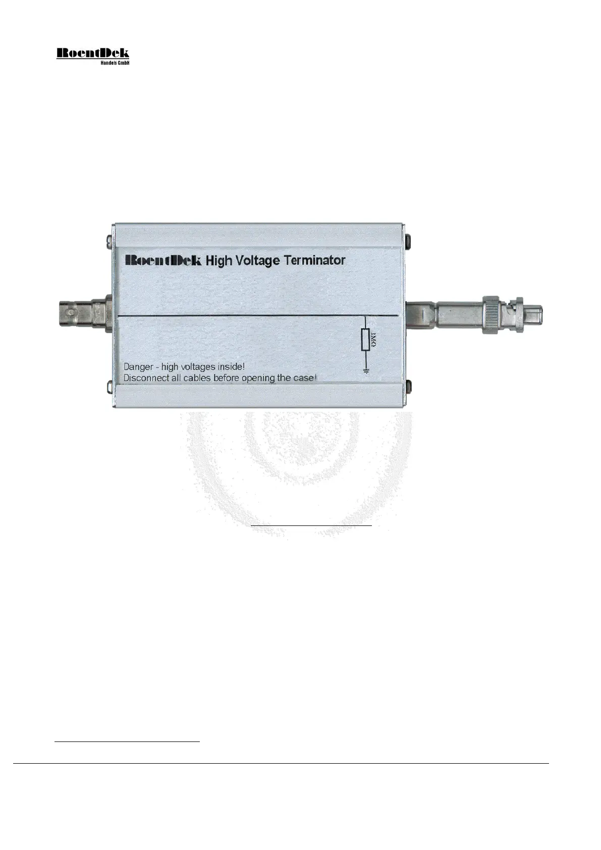
RoentDek can provide a passive so-called High Voltage Terminator box HVT. If such a unit is placed in the
cable connections between the (lower-bias) voltage supply output and the MCP bias input the “pull-away” effect is restricted
to a low-enough value (given by Equation 5.1) and it is then possible raising the bias to the desired value.
Figure 5.8: High Voltage Terminator
Here with 1MΩ resistor to ground and reverse SHV connector on one side.
In the following it is assumed that the MCP stack’s polarity shall be positive on both sides (for electron/negative particle
detection). Usually the MCP bias is connected via signal decoupling/terminating circuits containing blocking resistors R
Df
(at
MCP front and R
Db
*
(at MCP back). When introducing a High Voltage Terminator the following potential will be found at
MCP front side:
)(
)
(
DfDbMCP
HVT
DfHVT
backMCPfront
MCP
RR
RR
RR
U
U
++
+
+
×=
Equation 5.1
Often R
Df
can be neglected, likewise, the terms in parentheses are usually negligible in this formula.
The standard version of the HVT contains a 1MΩ resistor to “ground” and is optimized for electron detection purposes with
MCP front potential near +200V or higher. For typical MCP stack resistances > 20MΩ the minimum MCP front voltage due
to the “pull-away” effect will be < 200V and can actively be raised up to 1300V (maximum rating) with a high voltage supply.
Note, that the current to be drawn from the power supply may exceed its capability. A
RoentDek HV2/4 can only go up to
1000V when driving a 1MΩ resistor (less, if current limiter settings are engaged). For high potentials it is advisable adding
another 1MΩ in series, either by using a second HVT, or supplemented inside the HVT (separate resistors are available from
RoentDek). It is important to note that the effective MCP front potential may still differ from the set voltage in case of a
non-negligible value of R
Df
. Please refer to the RoentDek detector manual for determining this effect. The HVT4 version
contains a 10MΩ resistor rated for up to 4kV. It is typically used for applications with MCP front at a high negative potential
(e.g. -6kV via an SHV feedthrough and a special high voltage HFST) when the MCP back side is also at a negative potential
beyond -1kV) when the MCP back side is also at negative potential (above 1 kV). In this case, “U
MCP
front
” / “U
MCP back
” and
R
Df
/ R
Db
must be swapped in the above considerations and in Equation 5.1. The High Voltage Terminator is in this case
placed between the MCP back bias input and the corresponding high voltage supply output.
*
In the RoentDek FT12TP and HFSD/HFST decoupler circuits R
Db
is 1MΩ and R
Df
either 1MΩ or 10kΩ.
Page 74 of 83 MCP Delay Line Detector Manual (11.0.1304.1)