connections are firm. Make sure that the settings on the DLATR board are correct and correspond to the ATR19
version (ECL or NIM, see Chapter 3.2).
In order to change the settings for the signal level of timing outputs (ECL or NIM) it is required to remove the level control
boards from the base board after loosening the front panel from the housing. This procedure and especially the re-assembly is
complicated and not a recommended procedure for inexperienced users. If you want to change your ATR19 module between
ECL and NIM versions please contact
RoentDek.
These are the following options for the signal output levels on the ECL and NIM output connectors:
Standard NIM: JP1/JP3 and JP2/JP4 set, JP22/JP23 open (as in Figure 3.4)
The timing output from the CFD is present on the “NIM” LEMO connector as standard NIM level.
If JP1/JP3 is left open the CFD output signals will also be present on the upper pin (red dot) of the “ECL” LEMO connector
as the positive ECL+ level. Please inquire before you intend to use this option.
Standard ECL: JP22/JP23 set, JP1/JP3 and JP2/JP4 open
The timing output from the CFD is present on the “ECL” LEMO connector as standard (differential) ECL levels. The ECL+
level is found at the pin near the red dot and the ECL- at the lower pin. Additionally, the ECL- level is supplied via a 50Ω
resistor in line to the “NIM” LEMO connector for control (see Chapter 3.3)
If JP2/JP4 is set and JP22/JP23 is left open the ECL- level is directly present on the “NIM” LEMO connector without in-line
resistor. Please inquire before you intend to use this option.
If you change the settings of your ATR19 between ECL and NIM you must also change the settings on the DLATR boards
(see Chapter 3.2).
To close the top lid (ATR19-6/8-channel version), take off the rear panel again. Insert the top lid into the guiding slots and fix
the rear panel tight with the screws. For ATR19-2 refer to Chapter 3.6.
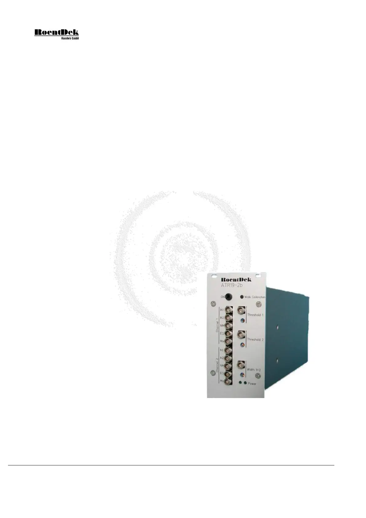
3.6 The ATR19-2(b) module
The ATR19-2(b) module is a 2-channel (1 DLATR board) version
of the above-described ATR19 module series. It measures 3HU
(19” rack height units) and has no internal mains adapter.
The ATR19-2b can be operated with the supplied 12V mains
adapter, which can supply several units (at least 4) chained in series
via rear panel connectors. For operation of the older version
ATR19-2, ±6V DC (600mA) need to be supplied via the rear panel
connector, e.g. from the SPS1(b).
All other functions / settings are identical to the ATR19-6 or
ATR19-8 module versions.
To open the module remove the screws on the front and rear panel
which fix the right side panel (the one with holes). Now you can
remove the side panel and have access to the DLATR board inside.
For complete disassembly and full access to all parts remove also
the remaining screws on front and rear panel.
Figure 3.9: ATR19-2b module
Page 42 of 83 MCP Delay Line Detector Manual (11.0.1304.1)