Now fix the stack with the plastic nuts gently and very carefully. Use only so much force (“hand-tight”) that the rings and
MCP cannot move any more.
Figure 1.14: Assembly of MCP-stack - Stage 3-2 (DLD40, DLD80 & HEX80)
The MCP holder stack can now be finally fixed with 4 spring clamps. Make sure that one of the rings is close to the cable
contact of the back ring and the other three at about 90° relative angle to that (see Figure 1.9). No clamp should be right
at the position of a contact pad on any side of the rings.
Figure 1.15: Assembly of MCP-stack - Stage 3-3 (DLD40, DLD80 & HEX80)
Now remove the plastic screws again. The MCP holder stack can be used as an independent unit.
Figure 1.16: Assembly of MCP-stack - Stage 3-4 (DLD40, DLD80 & HEX80)
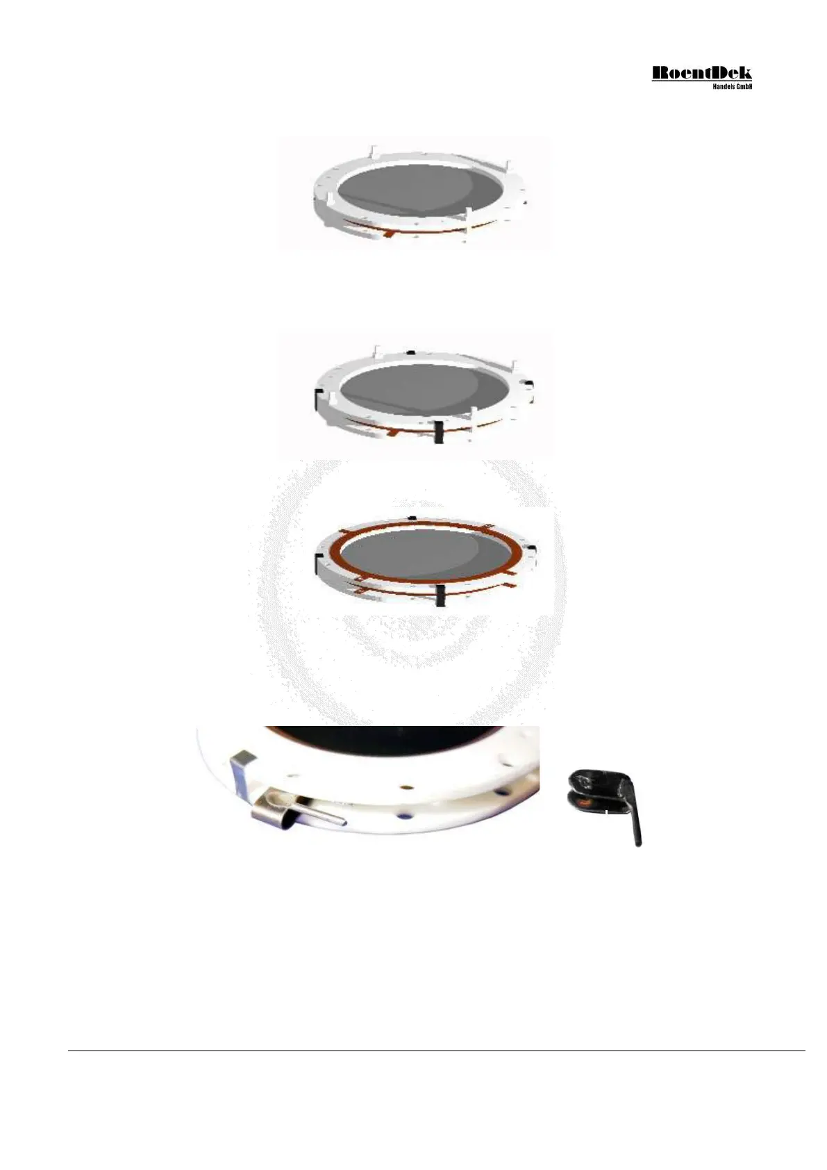
For MCP stacks with 3mm thickness the MCP back side can be contacted by a special spring clamp. Insert it between the
rings at the position of a contact pad around a hole on the rear ceramic ring, i.e. electrically in contact with MCP back.
Make sure that MCP front ring has no contact pad on the opposing side at the same position. The spring clamp has a 1mm
stub for a connector (obtainable from
RoentDek).
Figure 1.17: MCP stack with spring clamp for the MCP back cable (DLD40, DLD80 & HEX80)
4. Now the MCP-stack can be mounted to the anode by inserting it into the butterfly-shaped indent of the holder plate and
fixing it with the movable shields. Only uncoated parts of the ceramic ring shall rest on the holder plate, i.e. the spring
clamps and protruding contacts from the back ring must be located along the diagonal of the plate, not touching it.
MCP Delay Line Detector Manual (11.0.1304.1) Page 17 of 83