Depending on the connecting scheme of the MCP contact there may be mechanical conflicts for the mesh mounting and/or
potential electrical hazards for the detector operation at certain mesh voltages. We recommend contacting
RoentDek for
further advise when using a mesh close (i.e. < 3mm distance) to the MCP front ring.
The MCP back contact on the rear ceramic ring can be made in the same way as on the front ring. For most standard
RoentDek detector stacks with a total MCP stack thickness of 3mm (not for DLD40EP and DLD80eT/Hex75eT) the
cable for biasing the MCP stack’s back side can alternatively be connected via a contact spring clip (see Figure 1.17).
It is very important
• that no part of the screw/nut protrudes more than 0.8mm towards the holder plate (a screw tip must end in a recessed
nut or just on the nut edge). Use only countersunk M2 screws for fixing things on the ceramic rings.
• to rotate the ring on the holder plate such that the screw is located at or near the holes along the diagonal (see Figure
1.8). Any other contact or mounting screw (i.e. for a mesh) cannot be on the same azimuthal position later.
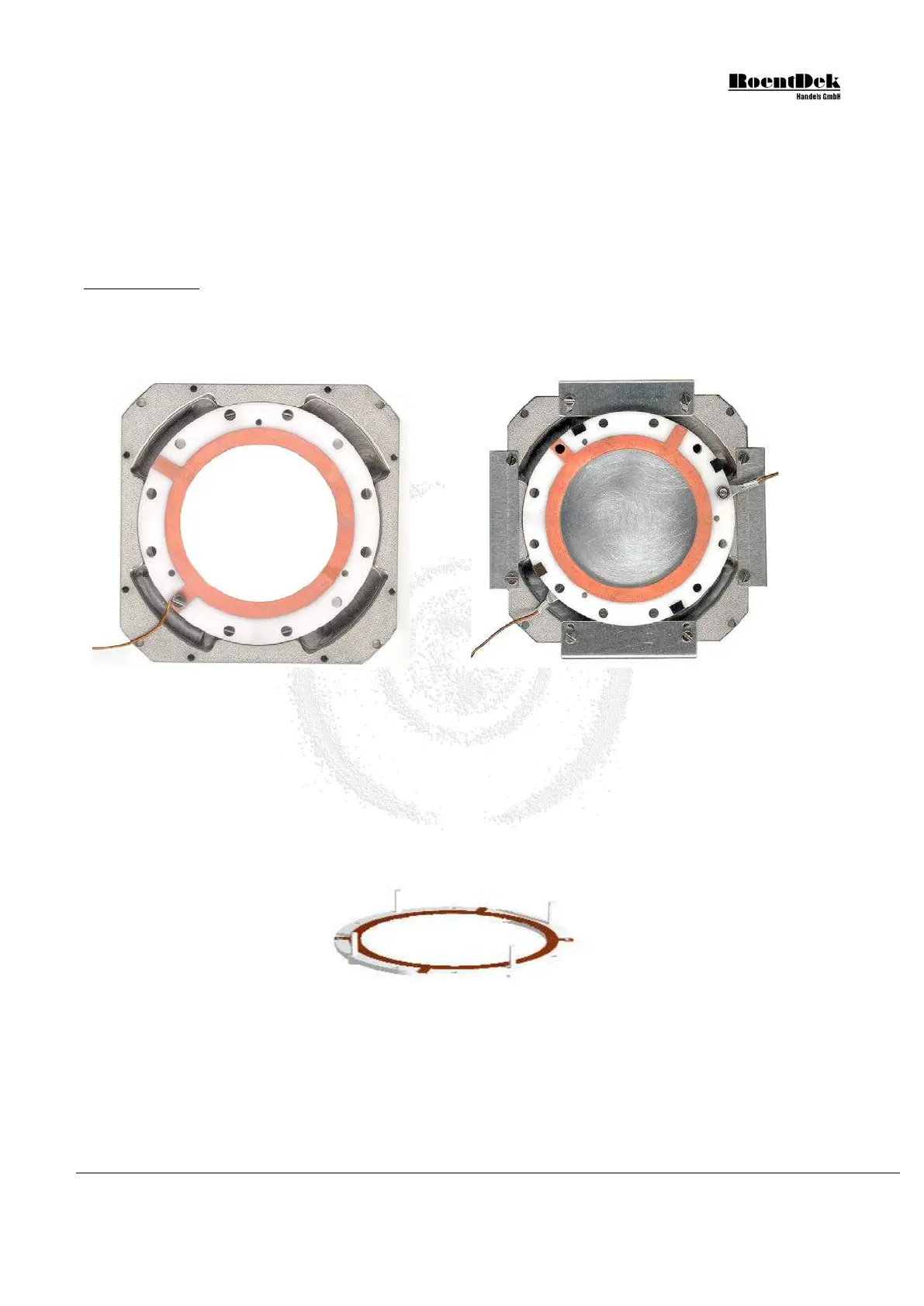
Figure 1.9: Recommended ring orientations on a DLD40 assembly (DLD80 & HEX80 similar). Left picture:
cable connection of this type without lug. Cable connection pads must rest in the recessed parts of the holder
plate near the diagonal. Right picture: the assembled MCP stack with recommended orientation. Here, lugs with
crimped wires crimped are used. Please follow the next figures/directions to achieve such a detector mounting
After having safely fixed the contact cable(s) on the ceramic ring(s):
In this and the following assembly drawings, no cables are shown.
1. Place the front ceramic ring (metallization on both sides), with the contact for MCP front side pointing upward, with
inserted plastic screws from below on a flat table:
Figure 1.10: Assembly of MCP-stack - Stage 1 (DLD40, DLD80 & HEX80)
2. Remove one MCP (for first stage of the stack) carefully from its transport package and place it centered onto the ceramic
ring. Unless otherwise noted any of the delivered MCPs can be used for this and will have a mark on the outer rim defining
the input (front) side, indicating the MCP pores’ tilt angle in the azimuthal plane. This side has to face down and will be in
contact with the front ceramic ring. Remember the position of the mark. The second (and possibly a third) MCP will be
placed with its mark also facing down and should be rotated by about 180 azimuthal degrees with respect to the mark
position on the MCP under it. In a side view cross section of the stack, the pores of the MCP would resemble a (broad)
MCP Delay Line Detector Manual (11.0.1304.1) Page 15 of 83