“v” shape (or chevron), or a “z” shape for triple stacking. Such an angle orientation is very important for proper stack
performance, however, any relative azimuthal angle between 150° and 210° will serve as well as having exactly 180° between
marks.
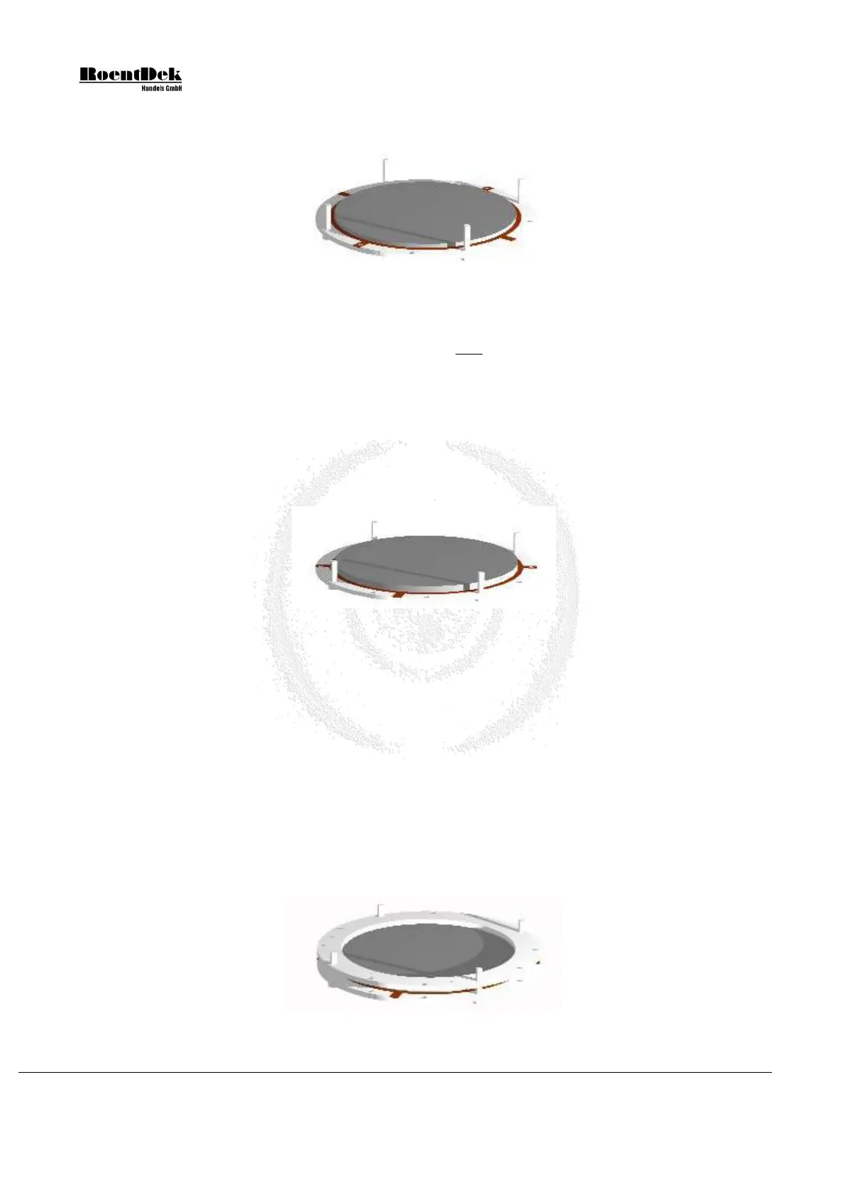
Figure 1.11: Assembly of MCP-stack - Stage 2a (DLD40, DLD80 & HEX80)
A shim ring may be placed between the MCP stages of the stack. Usually, the delivered MCPs will be matched in resistance
within 10% for direct stacking. If not, a shim ring with contact lug must be used with cable connection to a feedthrough for
bias via a high voltage supply. Please contact RoentDek in such a case. However, even for matched MCP placing a shim
ring can be recommended.
• DLD40, DLD80, HEX75 with 60:1/40:1 MCP: there is no intermediate contact ring recommended, the second
(and possibly third) MCP can be placed in direct contact with each other.
• HEX80 with 60:1 MCP: a shim ring can optionally be supplied to reduce the active MCP diameter to 75mm.
This is beneficial for some multi-hit applications.
• DLD40EP/DLD75eT, HEX75eT with 80:1 MCP: a shim ring may be used for reducing ion feedback and
increased gain at lower bias (but may affect temporal resolution adversely).
Figure 1.12: Assembly of MCP-stack - Stage 2b (DLD40(/2), DLD80 & HEX80/HEX75)
After possibly placing a shim ring on the first MCP the second (and optionally third) MCP can be stacked on top of the
first one, observing the position of marks (see above). Dust particles that may have settled on MCP surfaces can usually
be blown away by dry air over the surface.
It is especially important to avoid that dust particles settle between the MCP during assembly
.
Touch MCPs only with care along the rim, preferably with gloves. See also the Appendix of this manual for general MCP
handling. After the stack is piled you have to check if it is well centered, adjustments can be done by carefully shifting
individual MCPs sideways.
3. Place the second ceramic ring (with the MCP back contact facing down) carefully on the MCP-stack. The plastic rods will
guide the alignment.
Note, that the contact positions on the two ceramic rings must not oppose each other.
Figure 1.13: Assembly of MCP-stack - Stage 3-1 (DLD40, DLD80 & HEX80)
Page 16 of 83 MCP Delay Line Detector Manual (11.0.1304.1)