“HV In” bias. This is important to note when considering the effective voltage across the MCP stack and when calculating the
MCP resistance from the current flowing through the stack.
It is important to insure that the voltage across the HVZ is never inversed and “HV In” > “Back” > MCP front bias according
to normal detector operation. The use of the HVZ requires the “Back” output always being connected to the MCP back side
when applying voltage. Never directly short any of the HVZ outputs to ground in order to force this potential to zero. This
may cause severe damage to the HVZ circuit.
For operation in the standard configuration (as shipped) with all outputs sockets “Ref”, “Sig”, “Holder” and “Back” connected
to the detector ( e.g. via the
RoentDek FT12TP or FT16TP decoupling circuits) the bias applied to “HV In” is directly
connected with the “Sig” output socket, i.e. for the signal wire potential (U
sig
). “Ref” output provides the 36V more negative
U
ref
potential (i.e. with the same potential difference as provided by a RoentDek BA3 unit).
As described above the “Back” output provides the bias U
MCP
back
which is nominally 260V more negative with respect to “HV
In”. However, the effective bias on MCP back side may be lower (more negative) due to the voltage drop across the blocking
resistor in the signal decoupling circuit (typically 1MΩ, please refer to the delay-line detector manual for determining this
additional bias shift).
The bias pickup from the HVZ for the Holder potential (U
H
) can be adjusted between U
ref
and U
MCP
back
in steps of 56V by
selecting a jumper position (default: U
H
= U
MCP
back
+56V).
*
Before opening the HVZ, make sure to reduce all voltages to zero and then disconnect all cables from the HVZ. When
removing the cables while still on high potential, there might still be hazardous voltages stored within the HVZ's capacitors
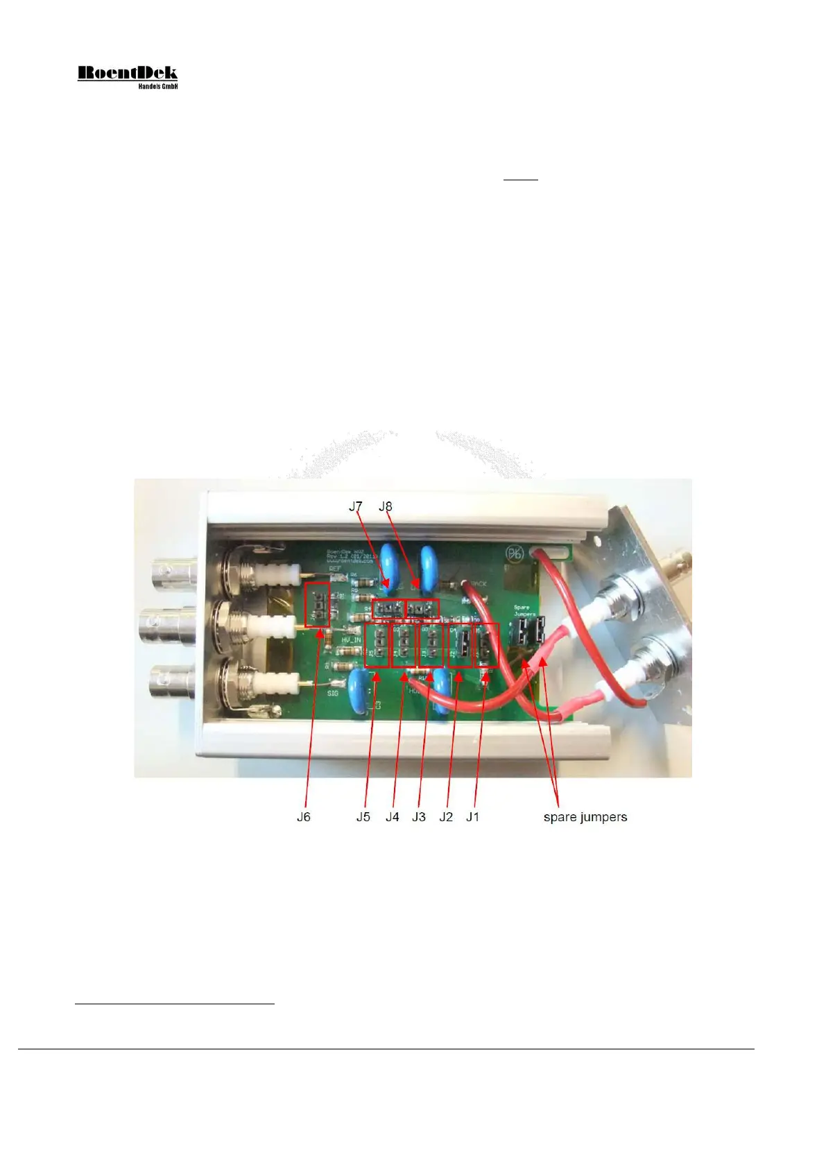
Figure 5.10: HVZ with jumper options.
The standard settings as displayed in Figure 5.10 (no jumpers on J6 to J8, one jumper on at positions J1 to J5) can be modified:
J1 to J5: jumper positions determining “Holder” potential. Only one jumper shall be set on J1 to J5.
jumper at J1: Holder and Back outputs provide the same potential U
H
= U
MCP
back
jumper at J2: default U
H
= U
MCP
back
+ 56V
jumper at J3: U
H
= U
MCP
back
+ 112V
*
Note that the detector’s Holder potential is not necessarily to be supplied through the HVZ. It can also be drawn from an
independent high voltage supply if linearity near the MCP edge needs optimization.
Page 76 of 83 MCP Delay Line Detector Manual (11.0.1304.1)