37
Reference Manual
00809-0100-4809, Rev DA
Section 2: Installation
September 2015
Installation
2. Place four
1
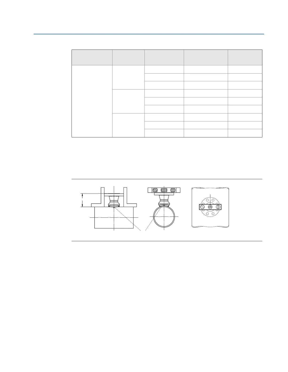
/4-in. (6-mm) tack welds at 90° increments. Check alignment of the
mounting both parallel and perpendicular to the axis of flow (see Figure 2-23). If
alignment of the mounting is within tolerances, finish weld per local codes. If outside of
specified tolerance, make adjustments prior to making the finish weld.
Figure 2-23. Alignment
A. Tack welds
3. If opposite side support is being used, center the fitting for the opposite side support
over the opposite side hole, gap
1
/16-in. (1.5 mm) and place four
1
/4-in. (6-mm) tack
welds at 90° increments. Insert the sensor into the mounting hardware. Verify that the
tip of the bar is centered in the opposite side fitting and that the plug will fit around the
bar. If the sensor is centered in the fitting and plug fits around the sensor, finish weld per
local codes. If alignment of the sensor does not allow enough clearance to insert the
opposite side plug, make the necessary adjustments prior to making the finish weld.
The Annubar sensor must be removed before welding or installing the opposite side
support plug.
4. To avoid serious burns, allow the mounting hardware to cool before continuing.
3
A
1 3.0-in. 150# RF 4.63 (117.5)
3 3.0-in. 300# RF 5.00 (126.9)
6 3.0-in. 600# RF 5.38 (136.6)
R
1 3.0-in. 150# RTJ 4.81 (122.2)
3 3.0-in. 300# RTJ 5.25 (133.4)
6 3.0-in. 600# RTJ 5.44 (138.2)
D
1 DN80 PN16 RF 3.85 (97.8)
3 DN80 PN40 RF 4.16 (105.7)
6 DN80 PN100 RF 4.95 (125.7)
1. Tolerances for the ODF dimension above a 10-in. (254 mm) line size is ±0.060-in. (1,6 mm). Below 10-in. (254 mm) line size is
±0.030-in. (0,8 mm).
Table 2-8. 485 and 585 Flange Sizes and ODF Per Sensor Size
485 Sensor size Flange type Pressure class
Flange size/
rating/type
ODF in.
(mm)
(1)
ODF
A