38
Reference Manual
00809-0100-4809, Rev DA
Section 2: Installation
September 2015
Installation
Step 4: Insert into pipe
1. After the mounting hardware has cooled, use the following steps for installation.
2. Assemble the sensor flange to the mounting flange using gasket, studs, and nuts.
3. Tighten the nuts in a cross pattern to allow even compression of the gasket.
4. Thread studs into Flange-Lok body.
5. To ensure the flowmeter contacts the opposite side wall, mark the tip of the sensor with
a marker. (Do not mark if the sensor was ordered with special-cleaned option code P2 or
PA.)
6. Insert the flowmeter into the Flange-lok body until the sensor tip contacts the pipe wall
(or support plug), rotating back and forth.
7. Remove the flowmeter.
8. Verify the sensor tip made contact with the pipe wall by ensuring that some of the
marker has been rubbed off. For special-cleaned bars, look for wear marks on the tip. If
the tip did not touch the wall, verify pipe dimensions and the height of the mounting
body from the OD of the pipe and re-insert.
9. Re-insert the flowmeter into the Flange-Lok body and install the first packing ring on
the sensor between the lock ring and the packing follower. Take care not to damage the
split packing rings.
10. Push the packing ring into the Flange-Lok body and against the weld retaining ring.
Repeat this process for the two remaining rings, alternating the location of the packing
ring split by 180°.
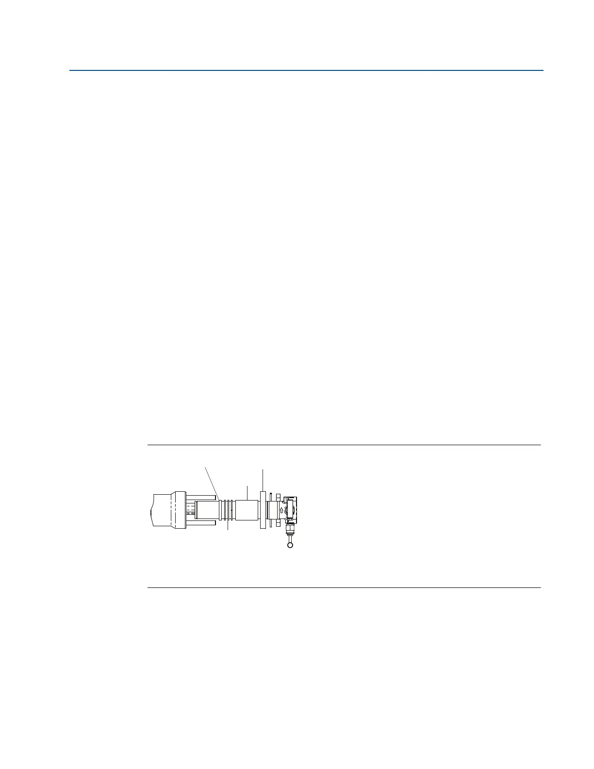
Figure 2-24. Packing Ring Detail
A. Retaining ring
B. Compression plate
C. Follower
D. Packing rings (3)