39
Reference Manual
00809-0100-4809, Rev DA
Section 2: Installation
September 2015
Installation
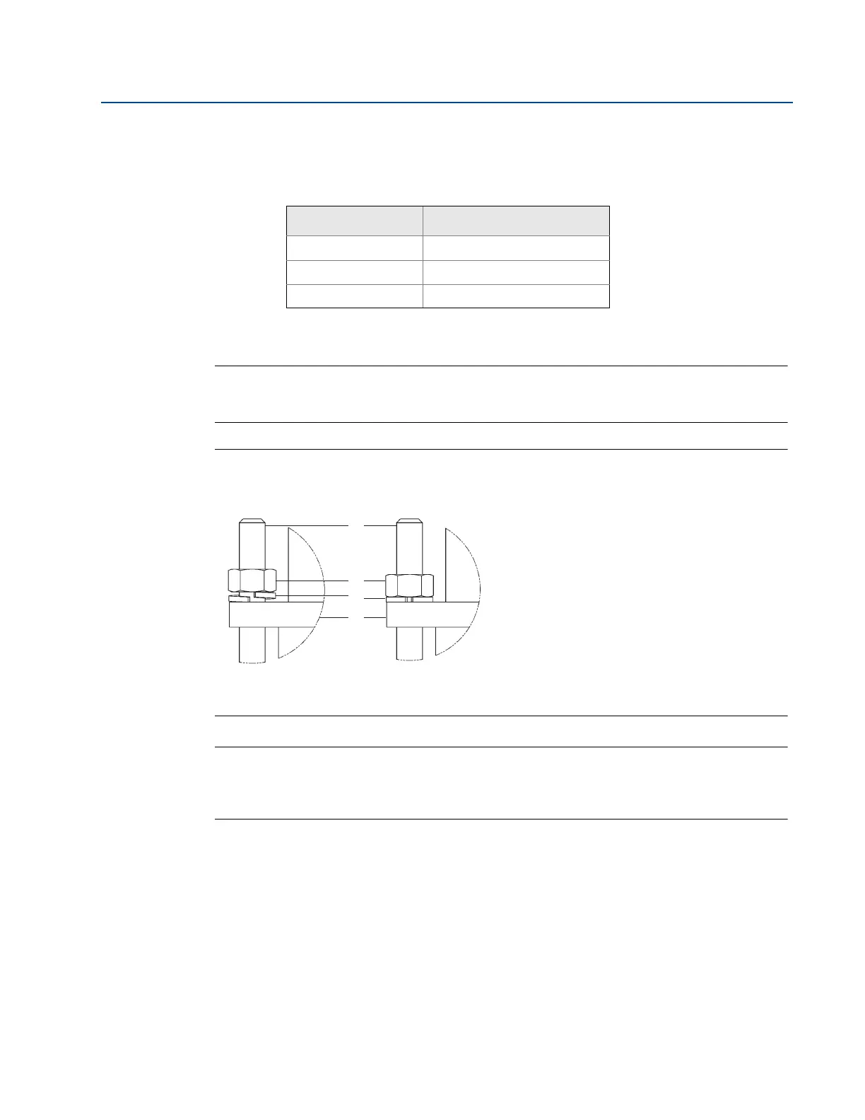
11. Tighten the nuts onto the studs:
a. Place the included split-ring lock washer between each of the nuts and the
compression plate. Give each nut one half (
1
/2) turn in succession until the split-ring
lock washer is flat between the nut and the compression plate. Torque is as follows:
b. Inspect the unit for leakage; if any exists, tighten the nuts in one-quarter (
1
/4) turn
increments until there is no leakage.
Note
On sensor size (1), failure to use the split-ring Lock washers, improper washer orientation, or
over-tightening the nuts may result in damage to the flowmeter.
Figure 2-25. Split-Ring Lock Washer Orientation
Note
Flange-Lok sealing mechanisms generate significant force at the point where the sensor
contacts the opposite pipe wall. Caution needs to be exercised on thin-walled piping (ANSI
Schedule 10 and below) to avoid damage to the pipe.
Sensor size Torque
1 40 in/lb (4.52 Nm)
2 100 in/lb (11.30 Nm)
3 250 in/lb (28.25 Nm)
Before tightening After tightening
A. Stud
B. Nut
C. Split ring lock washer
D. Compression plate
A
B
C
D