40
Reference Manual
00809-0100-4809, Rev DA
Section 2: Installation
September 2015
Installation
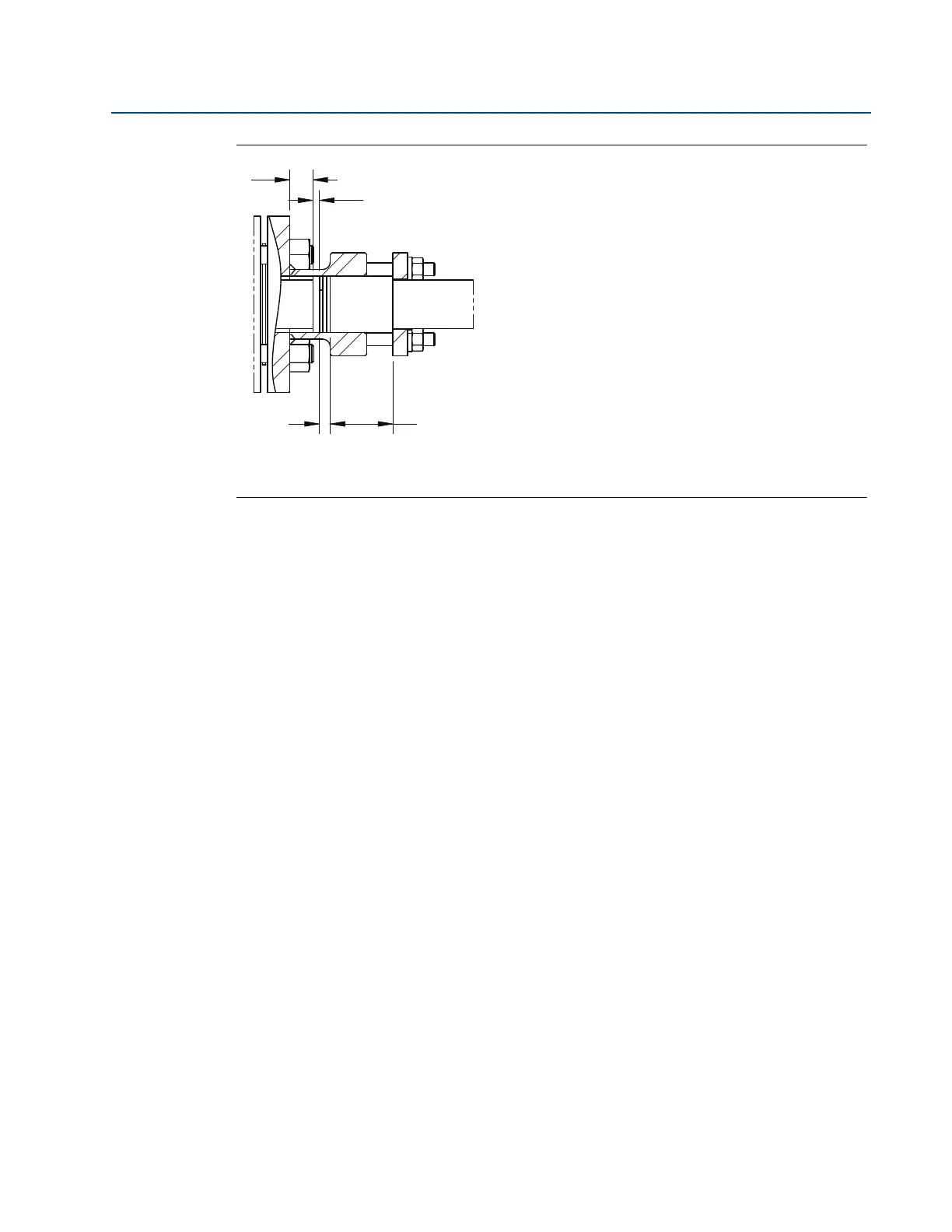
Figure 2-26. Complete Installation of Flange-Lok
Figure 2-26 shows a view of the Flange-Lok Annubar sensor when installation is completed.
Please note that there should be a gap between the Flange-Lok Body and the Weld Ring.
Step 5: Mount the transmitter
Direct mount head
With valves
1. Place PTFE O-rings into grooves on the face of head.
2. Align the high side of the transmitter to the high side of the Annubar sensor
(“Hi” is stamped on the side of the head) and install.
3. Tighten the nuts in a cross pattern to 400 in-lb. (45 N-m).
Without valves
1. Place PTFE O-rings into grooves on the face of head.
2. To install a manifold, orient the equalizer valve or valves so they are easily accessible.
Install manifold with the smooth face mating to the face of the head. Tighten in cross
pattern to a torque of 400 in-lb. (45 N-m).
3. Place PTFE O-rings into grooves on the face of the manifold.
4. Align the high side of the transmitter to the high side of the Annubar sensor
(“Hi” is stamped on the side of the head) and install.
5. Tighten the nuts in a cross pattern to 400 in-lb. (45 N-m).
A. Gap
B. Packing rings (3)
C. Weld ring
D. Follower