BRP-Rotax
MAINTENANCE MANUAL LINE
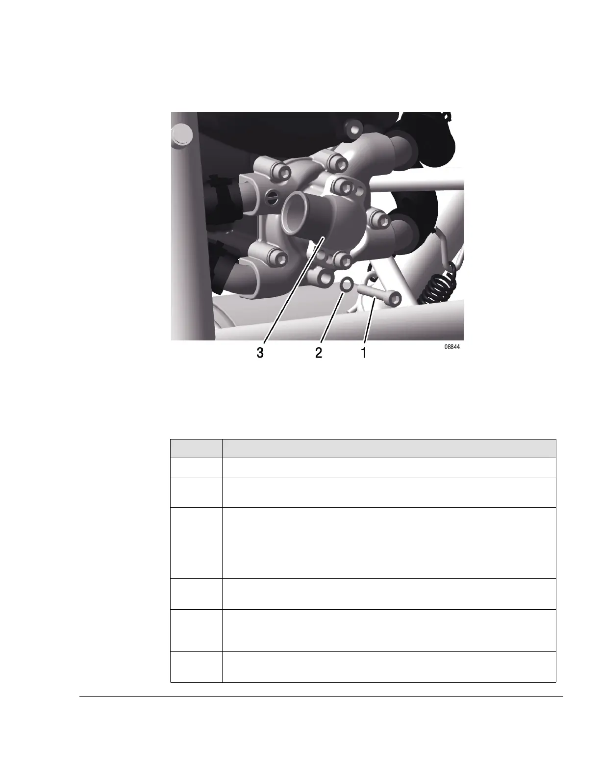
Instruction To replace the coolant the following steps are necessary:
Figure 7.14: Replacing the coolant TYPICAL
1
Attachment screw (stainless steel)
2
Gasket ring
3
Water pump
Step
Procedure
1 Open the radiator cap on the expansion tank.
2
Remove the bottom attachment screw (1) (with sealing ring (2) ) of water
pump (3).
3 Drain the engine coolant.
NOTE
If the radiator is located below the engine, also detach the lowest
positioned coolant hose.
4
Fit attachment screw (stainless steel) along with a new sealing ring. Tighten
to 10 Nm (89 in.lb).
5
If the coolant is being replaced with a different type, (OAT, IAT) the cooling
system must be flushed. See chapter 12-20-00 section Flushing the cooling
system.
6 Refill newly mixed coolant into the expansion tank (highest point of the cool-
ing system). See chapter 12-10-00 section Coolant check/replenish.
Effectivity: 912 i Series
Edition 2/Rev. 0
12–20–00
Page 25
September 01/2018

 Loading...


