76-00-00
page 46
May 01/2007
Effectivity 914 Series
Edition 1 / Rev. 0
d02626
BRP-Rotax
Maintenance Manual
a) Airbox pressure sensor:
See Figs. 76-44 and 76-45.
On engines with an airbox of older configuration, the installa-
tion location of the airbox pressure sensor (2) depends on the
aircraft type and is limited by the length of the wiring harness.
On engines with an airbox of newer configuration, the airbox
pressure sensor (2) is integrated in the airbox. See SI-914-013
and SI-914-015, “Introduction of a new airbox“, latest issue.
■ CAUTION: The sensor is designed for a pressure range of
500 hPa to 2500 hPa and max. pressure must
not exceed 3500 hPa.
If the max. pressure is exceeded during the course of measur-
ing, the sensor must be replaced.
When taking the following readings, the plug connection to the
wiring harness must be disconnected and reestablished im-
mediately after completion of the checks. The same applies for
the air pressure hose.
The easiest way to check the function of the two pressure
sensors is to use the communication program. If this program
is not at your disposal, the following static checks can be
carried out.
- Inspect for physical damage.
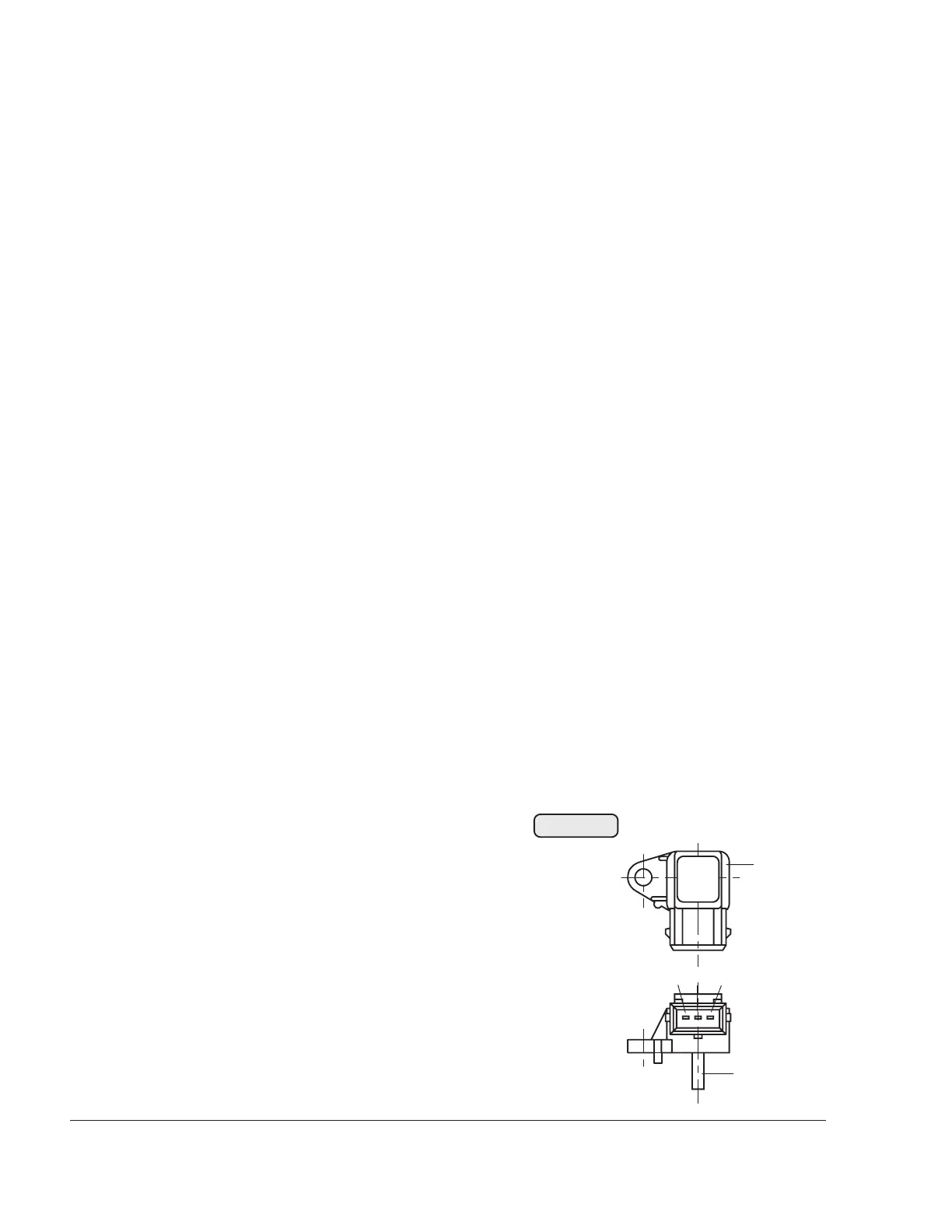
- Static check for function of airbox pressure sensor:
Allocation of connections for
test set-up / legend to Fig. 76-44
(3) Measuring voltage output Ua
(4) Ground (øV)
(5) Voltage supply Us
min. + 3 V, max. + 15 V
(6) Pressure connection
00058
966 502
airbox
pressure
2
345
6
Fig. 76-44

 Loading...


