Effectivity 914 Series
Edition 1 / Rev. 0
76-00-00
page 5
May 01/2007
d02626
BRP-Rotax
Maintenance Manual
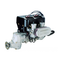
The following diagram shows the pressure regulating sequence for the
newer TCU versions (TCU No. 966741 or higher) (Fig. 76-2).
The airbox target pressures for engine operation with newer TCU
versions:
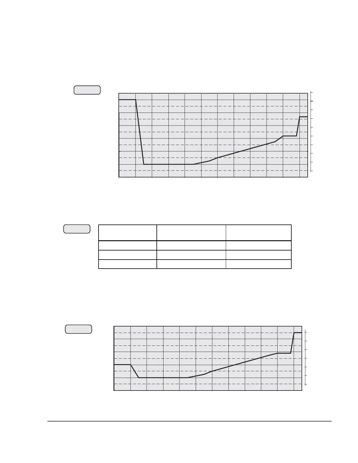
The following diagram (Fig. 76-4) illustrates the relationship between
the throttle valve position and the nominal airbox pressure for older
TCU versions (TCU part no. 966470 - 966473).
engine performance throttle potentiometer Airbox-nominal pressure
idle ~ 0 % 1500 hPa (44,3 in. HG)
continuous output 100 - 108 % 1220 hPa (36,0 in. HG)
take-off performance 110 - 115 % 1370 hPa (40,5 in.HG)
00952
Fig. 76-3
Fig. 76-2
00170
28
1400
1300
1200
1100
1000
900
hPa
0 10 20 30 40 50 60 7 0 80 90 100 110 115 %
30
32
34
36
38
46 in. HG
1500
40
42
44
28
1400
1300
1200
1100
1000
900
hPa
0 10 20 30 40 50 60 7 0 80 90 100 110 115 %
30
32
34
36
38
40 in. HG
04813
Fig. 76-4
 Loading...