Effectivity 914 Series
Edition 1 / Rev. 0
76-00-00
page 49
May 01/2007
d02626
BRP-Rotax
Maintenance Manual
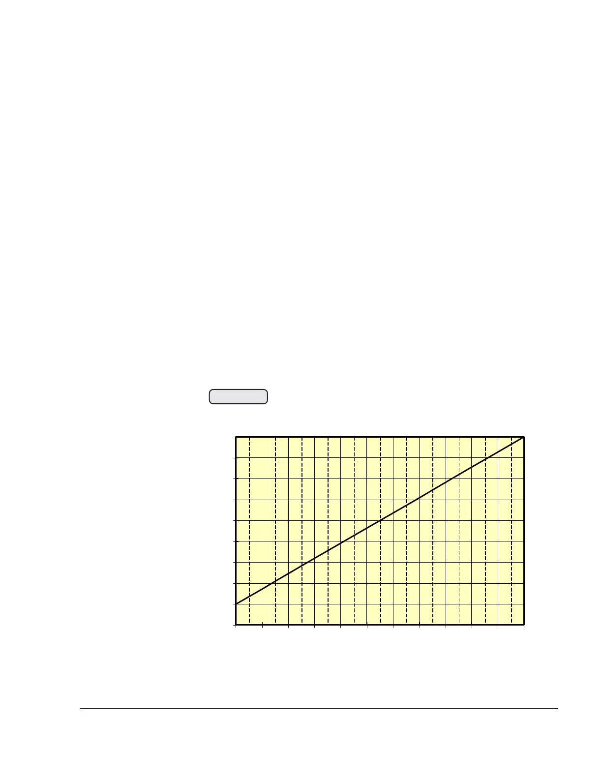
Test set-up
Connect pin (4) to ground and connect pin (5) to positive side
of voltage supply Us. Apply test pressure to sensor (input 6)
Take reading of output voltage between pin (4) and pin (3).
Divide the measured out put voltage (Ua) by the supply
voltage (Us).
◆ NOTE: Calculation of this pressure ratio is required
since the diagram is effective over a whole
voltage range and not just for a single voltage.
Enter this value in the table Ua/Us. A pressure can be read off
at the intersection of the straight lines.
Max. allowance ± 60 hPa
■ CAUTION: In the event of physical damage or resistance
readings outside allowance, replace the part
without delay.
0,0
0,1
0,2
0,3
0,4
0,5
0,6
0,7
0,8
0,9
100
200
300
400
500
600
700
800
900
1000
1100
1200
Druck [hPa] absol
ressure absolute
Ua/Us
00441
Fig. 76-47
 Loading...