EbV Product documentation THETA NORM/UNIT
8-33
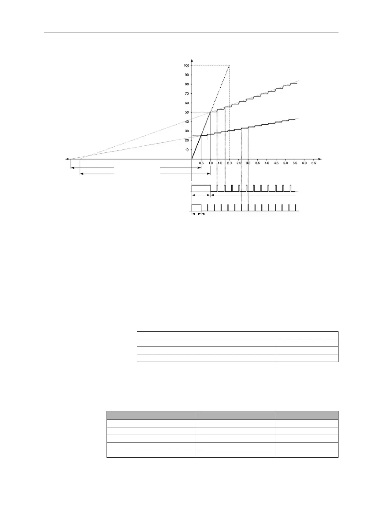
Example of the coaction of P-band, I-band, adjustment time and sample time
8.2.3.4.1 End position function actuator
This function determines the type of control signal in the end positions OPEN and CLOS of each actuator.
1 = Continuous voltage signal at connector OPEN or CLOS at the respective end position
2 = De-energized in end position OPEN or CLOS respectively
When the limit stop of the actuator is reached (0 / 100 %), the actuator is in idle state
(STOP). To balance the running time tolerancies, a drain function of 100 % of the set
mixer running time takes place after reaching the limit stop.
Recommendation for the basic setting of the adjustment time in different heating systems:
If the parameter for the control of the limit stop = 2, the position signal (OPEN or CLOS) is sent after the
absolute valve position is recognised and the valve is at the limit stop (0 / 100 %) (display STOP). Just in
case, a drain function of 100 % of the set mixer running time takes place after reaching the limit stop. This
function ensures that the valve is at the required limit stop.
Application Adjustment time
Floor heating and other static heating surfaces 10 - 30 min
Radiator heating 6 -10 min
Convector heating 3 -6 min
Operation:
Note on operation Key / parameter tree Parameter
Proportional band Xp MIX. VALVE-1 / 2 PARAMETER 18
Sample time Ta MIX. VALVE-1 / 2 PARAMETER 19
Integral action time Tn MIX. VALVE-1 / 2 PARAMETER 20
Actuator Running Time MIX. VALVE-1 / 2 PARAMETER 21
End position function actuator MIX. VALVE-1 / 2 PARAMETER 22
Step response to different control deviations
(open control circuit, actuator pulled off)
Integral action time Tn=7 min
Sample time Ta=20 sec
Mixer running time = 2 min
The P-pulse, which is proportional to the control
deviation, is followed by further actuator pulses if the control
deviation was not eliminated at that point (I-band).
The integral action time remains constant for different
control deviations.
Mixer opening (%)
Position OPEN
Actuator characteristics
For control deviation 50%
Integral action time Tn=7
Actuator characteristics
For control deviation 25%
Integral action time Tn=7
Adjustment time Tn
Adjustment time Tn
Actuator pulses for control deviation (X
w
= 50%)
Actuator pulses for control deviation (X
w
= 25%)
P-band
I-band
Action time (min)