EbV Product documentation THETA NORM/UNIT
12-5
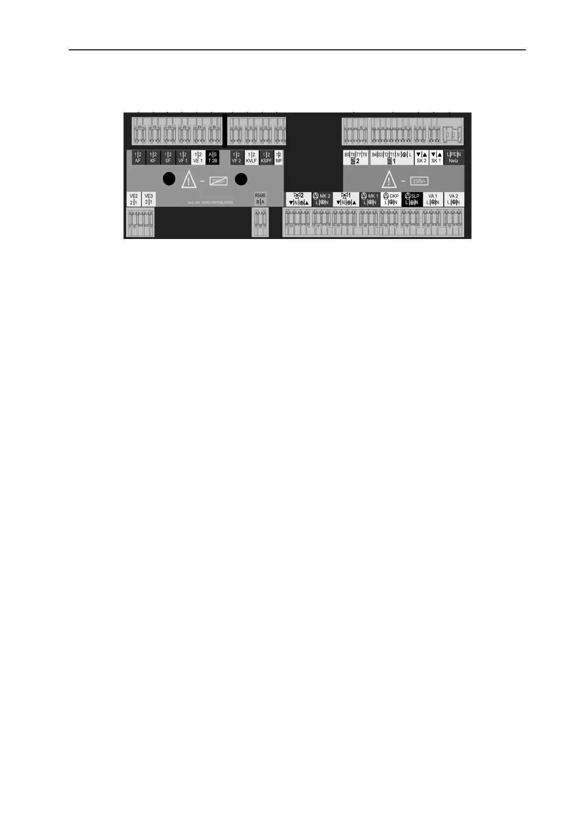
12.2.3 Electrical connection
230 V~ Connections Sensor and data bus connections
01 - Mains 230V~ +6/-10%, 50 Hz 14 - Outdoor sensor
02 - Safety circuit 1 (burner loop) 15 - Heat generator sensor/boiler sensor
03 - Safety circuit 2 (burner loop) 16 - DHW sensor
04 - Burner 1 (single step boilers) 17 - Flow sensor for mixed heating circuit 1
05 - Burner 2 (double step boilers) 18 - Flow sensor for mixed heating circuit 2
06 - Direct circuit pump 19 - Variable input 1
07 - Domestic hot water charging pump 20 - Variable input 2
08 - Pump for mixed heating circuit 1 21 - Variable input 3
09 - Actuator mixing valve 1 22 - Solar panel flow sensor
1)
10 - Pump for mixed heating circuit 2 23 - Solar tank sensor
1)
11 - Actuator mixing valve 2 24 - Pulse input
12 - Variable output 1 25 - Data bus T2B
depending of programmation
(see level HYDRAULIC)
26 - Data bus RS 485
2)
13 - Variable output 2
depending of programmation
(see level HYDRAULIC)
1)
Solar application only
2)
high efficiency condensing boilers only