EbV Product documentation THETA NORM/UNIT
12-3
12.2 Mounting instructions for UNIT type
12.2.1 Mounting UNIT
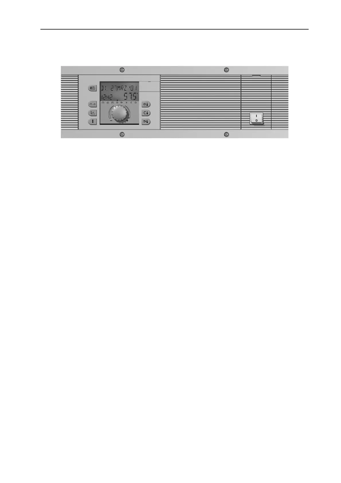
The boiler control panel is completely prewired and will be mounted from the front
side into the panel cut-out of the boiler after finishing the electrical wiring. The panel
is fastened with the four enclosed screws.
Removal is done in opposite direction.
The sensor of the safety temperature limiter as well as the boiler sensor will be
inserted into the sensor immersion pocket of the boiler.
Caution: Do not crease or damage the capillary tubing.
For further information see documentation of the boiler manufacturer.
Accessories
on demand: For easier installation, optional swing-out aids can be ordered. These aids will be
snapped into both left and right sides of the panel and prevent that the panel falls
down when opening.