EbV Product documentation THETA NORM/UNIT
12-2
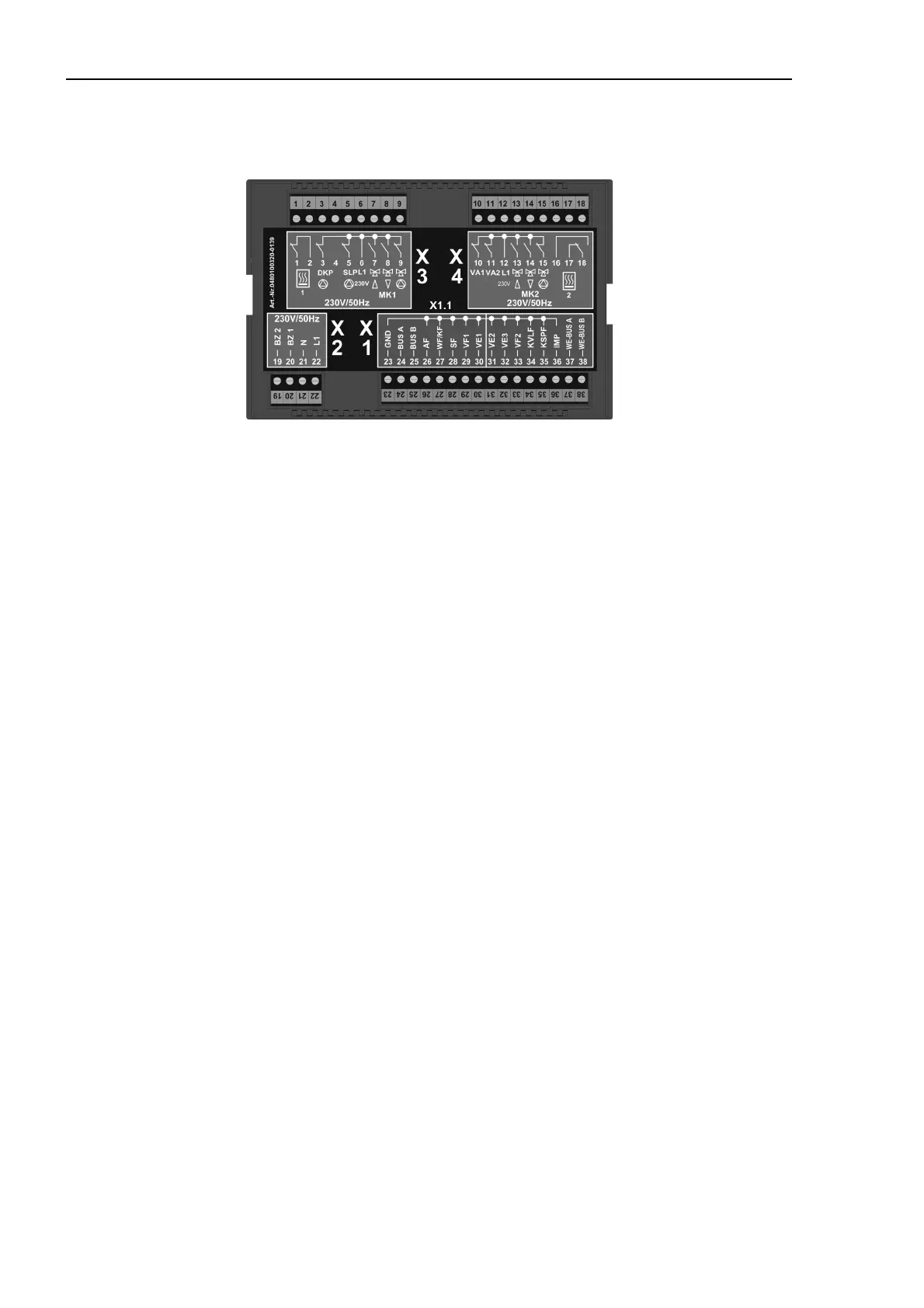
12.1.2 Electrical installation
230 V~ Connections Sensor and data bus connections
1 - Floating exit for heat generator, output 23 - Ground for data bus and sensors
(stage 1) 24 - Data bus signal A
2 - Floating exit for heat generator, input 25 - Data bus signal B
(stage 1) 26 - Outdoor sensor
3 - Direct circuit pump 27 - Heat generator sensor/boiler sensor
4 - Coded plug 28 - DHW sensor
5 - Domestic hot water charging pump 29 - Flow sensor for mixed heating circuit 1
6 - L 1 / 230 V 30 - Variable input 1
7 - Mixing valve 1 OPEN 31 - Variable input 2
8 - Mixing valve 1 CLOSED 32 - Variable input 3
9 - Pump for mixed heating circuit 1 33 - Flow sensor for mixed heating circuit 2
10 - Variable output 1 34 - Solar panel flow sensor
1)
11 - Variable output 2 35 - Solar tank sensor
12 - L 1 / 230 V 36 - Pulse input
13 - Mixing valve 2 OPEN 37 - Heat generator-data bus A
14 - Mixing valve 2 CLOSED 38 - Heat generator-data bus B
15 - Pump for mixed heating circuit 2
16 -
17 - Floating exit for heat generator, output -
(stage 2)
Mounting into boilers
See technical documentation of boilermanufacturer
Wall mounting
See technical documentation wall mounting set
THETA WG
1)
Solar application only
18 - Floating exit for heat generator, input -
(stage 2)
19 - Operat. hours counter burner -
(stage 2)
20 - Operat. hours counter burner -
(stage 1)
21 - N / 230 V mains
22 - L 1 / 230 V mains