EbV Product documentation THETA NORM/UNIT
9-7
9.3 Expanding the system by several standard units
9.3.1 Examples with several controllers
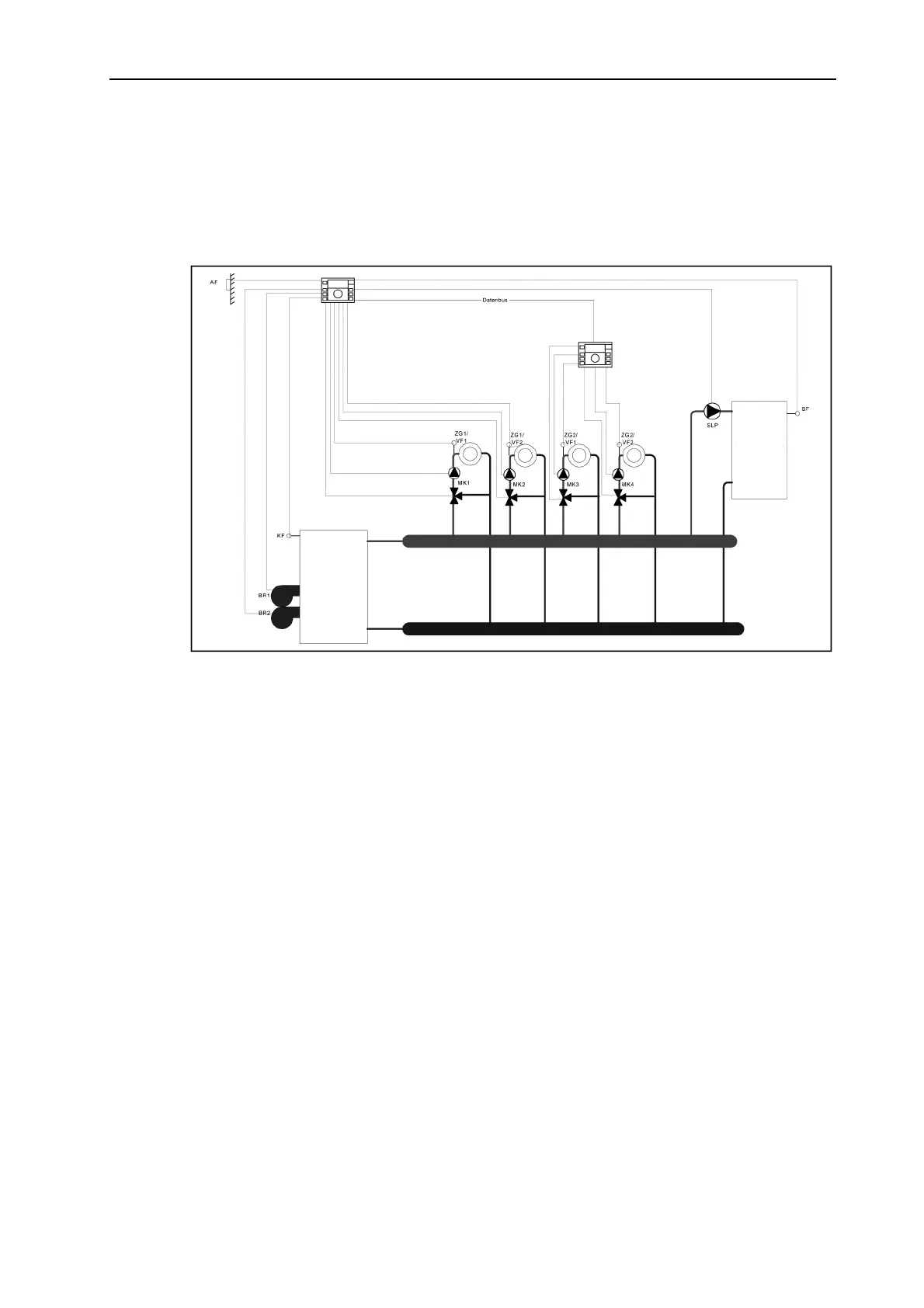
Example 1: Heating system with 2 stage heat generator, DHW control, and 4 mixed circuits. The
following diagram shows the hydraulic system.
The following components will be connected to the first controller with busadress 10:
• Outdoor sensor
• Stage 1 and 2 of the burner
• Boiler sensor
• DHW sensor
• Domestic hot water charging pump
• Mixer pump, mixer open / closed and flow sensor of heating circuit 1
• Mixer pump, mixer open / closed and flow sensor of heating circuit 2
The following components will be connected to the second controller with busadress
20:
• Mixer pump, mixer open / closed and flow sensor of heating circuit 3
• Mixer pump, mixer open / closed and flow sensor of heating circuit 4
Boiler
DHW tank