EbV Product documentation THETA NORM/UNIT
10-5
10.3.5 Operation with boiler control (new)
THETA controllers with communicative heat generator interfaces (..C..) enable
connecting more than one heat generator per controller. The cascade control in the
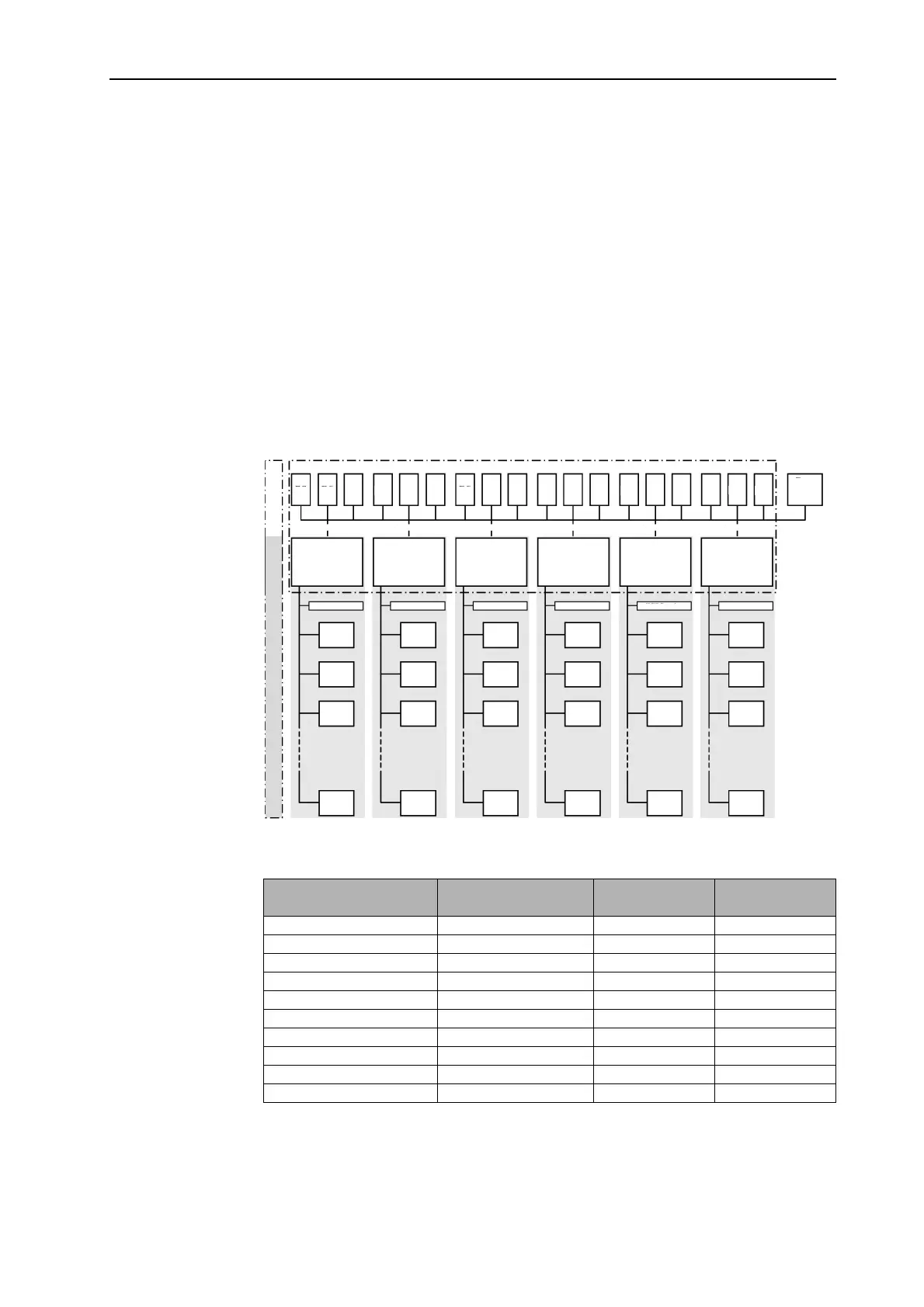
THETA system comprises a main cascade and, depending on the plant design, one
or more subcascades.
The main cascade is controlled directly by the cascade manager (address 10) via the
THETA system bus (T2B). Every participant in this cascade is a THETA controller
NORM or UNIT. The parameterization of the cascade settings is carried out at the
cascade manager. Specific settings for the heat generators are carried out at the
corresponding standard unit NORM or UNIT.
The subcascade is controlled via the H-GEN bus (heat generator bus). Usually,
several heat generators are addressed either via the interface (e.g. MCBA) or
directly. Because only one parameterization is possible for heat generators in
THETA, the settings are identical for all H-GEN in the subcascade.
System overview:
Example for addresses:
Address THETA N/U H-GEN type H-GEN address Stage number
cascade
10 MCBA 1 1
10 MCBA 2 2
10 MCBA 4 3
10 MCBA 5 4
10 MCBA 7 5
20 MCBA 1 6
20 MCBA 3 7
20 MCBA 5 8
20 MCBA 6 9
20 MCBA 7 10
Subcascade
Main cascade
RS
RS
RS
RS
RS
RS
RS
RS
RS
RS
RS
RS
RS
RS
RS
RS
RS
RS
Gate-
way x
T2B data bus
T2B data bus
T2B data bus
T2B data bus
T2B data bus
T2B data bus
THETA
Norm/Unit
2233BVVC
C-management
THETA
Norm/Unit
2233BVVC
THETA
Norm/Unit
2233BVVC
THETA
Norm/Unit
2233BVVC
THETA
Norm/Unit
2233BVVC
THETA
Norm/Unit
2233BVVC
Manager
H-GEN data bus
H-GEN data bus
H-GEN data bus
H-GEN data bus
H-GEN data bus
H-GEN data bus
H-GEN
H-GEN
H-GEN
H-GEN
H-GEN
H-GEN
H-GEN
H-GEN
H-GEN
H-GEN
H-GEN
H-GEN
H-GEN
H-GEN
H-GEN
H-GEN
H-GEN
H-GEN
H-GEN
H-GEN
H-GEN
H-GEN
H-GEN
H-GEN