EbV Product documentation THETA NORM/UNIT
10-6
Information display: If a subcascade is recognized, the standard unit shows a detailed information
display.
Detailed temperature display heat generator:
Additional display if the rotary pushbutton is pressed during the heat generator
temperature display:
Status display heat generator:
Additional display if the rotary pushbutton is pressed during the operating status
display:
Explanations: Required stages
number of stages calculated by the energy management for controlling
Recognized stages
number of all heat generator stages (main cascade and subcascade, 2-stage boilers
are counted as two stages) recognized via the data bus
Activated stages
number of active heat generator stages in cascade
Available stages
If individual stages are not available, e.g. due to an outdoor temperature lock or an
external heat generator block, the number of available stages is different than the
number of recognized stages.
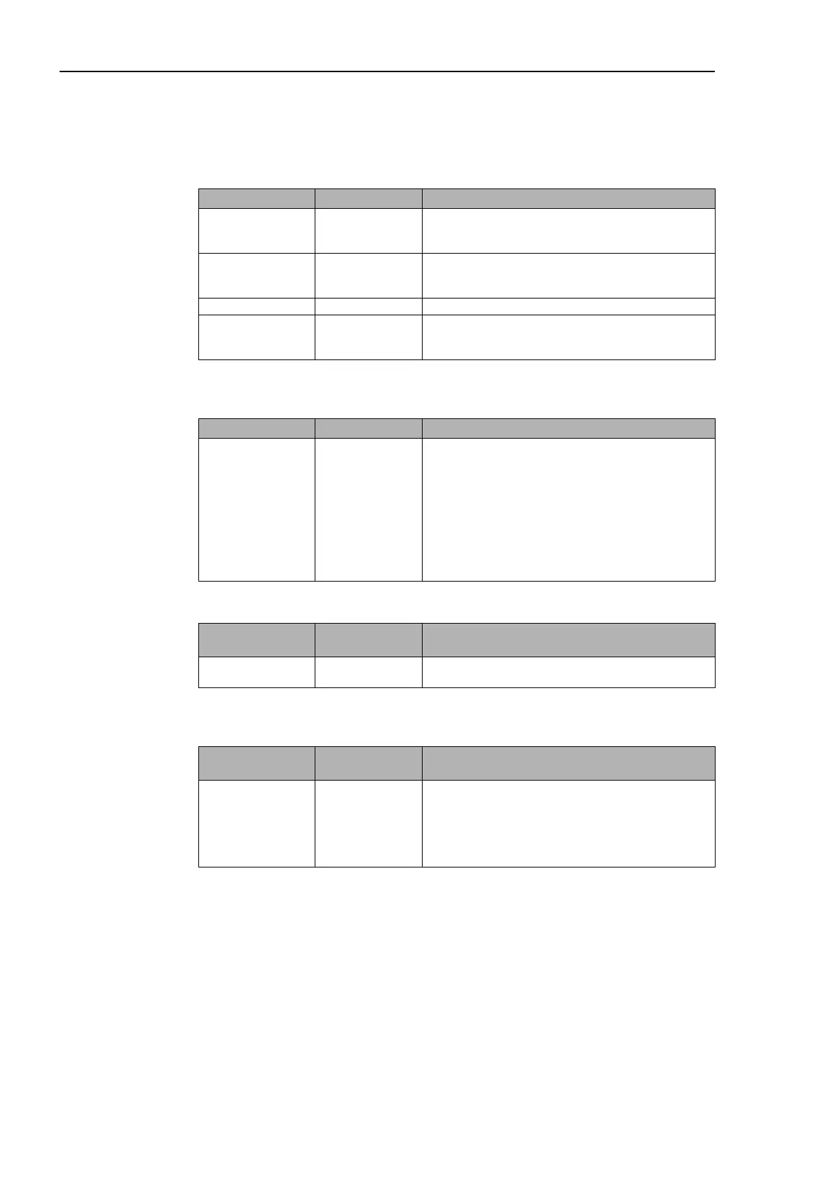
INFORMATION Display value Notes
Heat generator
temperature H-GEN
address 1
HEAT GENER.
ADR-1 actual
value
Combined display of heat generator address and actual
flow temperature of the boiler control with the address 1
Heat generator
temperature H-GEN
address 2
HEAT GENER.
.ADR-2 actual
value
Combined display of heat generator address and actual
flow temperature of the boiler control with the address 2
.... .... ....
Heat
generatortemperatur
e H-GEN address n
HEAT GENER.
ADR-N actual
value
Combined display of heat generator address and actual
flow temperature of the boiler control with the address n
INFORMATION Display value Notes
Heat generator
temperature H-GEN
adddress n
HEAT GENER.
setpoint op.cond.
• H-GEN setpoint displayed at bottom left
• "%" display, if capacity limitation on, bottom left
• Operating conditions displayed at bottom right:
- SET (requirement present, no flame
present)
- ON (requirement present, flame present)
- MANU (no requirement present, flame
present)
- OFF (no requirement present, no flame
present)
INFORMATION Display values /
-examples
Notes
Operating status
heat generator
HEAT GENER.
OFF/ON
Information on the switching state of the multiple stage
heat generator
INFORMATION Display values /
-examples
Notes
Operating status
heat generator
HEAT GENER.
SG/SE SA/SV
Combined display with information on the cascade
stages:
SG=required stages
SE=recognized stages
SA=activated stages
SV=available stages