EbV Product documentation THETA NORM/UNIT
5-1
5 Operation
5.1 User interface
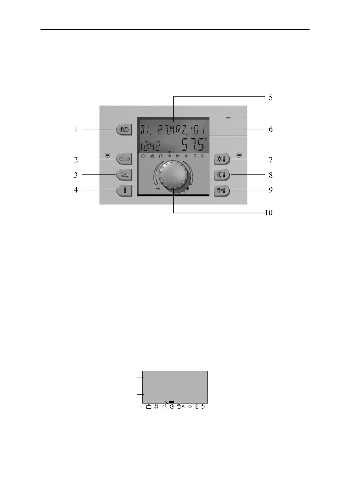
Display and operating instruments
1 – Key for emission measurement and manual operation
2 – "Operating mode" key for all heating and set back modes
3 – "Heating curve" key
4 – "Information" key for the display of temperatures and operating modes
5 – Multi-functional Display
6 – Cover clip for the service jack with labelling
7 – Daytime Room Temperature
8 – Night-time Room Temperature
9 – DHW daytime temperature setpoint
10 – Rotary pushbutton (push - turn)
5.1.1 Basic display
The display illumination is activated by any key, or the rotary pushbutton and switches off after a longer
period of inactivity.
When the plant is started or after a power cut, a segment test + fault diagnosis is carried out. After this test,
the software version and the device type are displayed briefly.
TH. 20.SEP. 01
1.47
o
c
40.0
Date
Time
Active operating mode
Operating mode symbols
Heat generator temperature