EbV Product documentation THETA NORM/UNIT
5-21
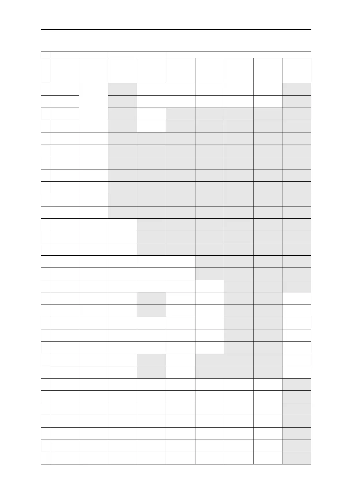
5.4.1 Level and Parameter overview
Programming Configuration Parameterization (Heating circuits, controlled systems)
Parameter
Nr.
TIME-
DATE
TIME-
PROGRAMS
Hydraulic
SYSTEM
DH
W (..B..)
UNMIXED
CIRC(..2..)
MIX.VALVE1
(..3..)
MIX.VALVE2
(..33.)
HEAT
GENER.
(..2.., ..22..)
1 Time (h/min)
See time
program
programming
Hydraulic
diagram
Language
DHW economy
temperature
Reduced
Operational mode
Reduced
Operational mode
Reduced
Operational mode
H-GEN type
2 Year
Output SOL-P
Enable time
programs
Legion.prot.
(day)
Heating system
(exponent)
Heating system
(exponent)
Heating system
(exponent)
Start-up
protection
3
Day-
Month
Output MC1 Control mode
Legion. prot.
(time)
Enable room
influence
Enable room
influence
Enable room
influence
Min. temp.
limit H-GEN
4
Change
Su-Wi Auto
Output MC1
Summer
switch-off
Legion. Prot.
(temperature)
Room factor Room factor Room factor
Maximum
temp. limit
5
Output HC
System frost
protection
DHW sensor
type
Adaptation
Heating curve
Adaptation
Heating curve
Adaptation
Heating curve
Minimum temp.
limiting mode
6
Output VO-1
Demand
contact VI-1
DHW max.
temp. limit
Opti-
mization
Opti-
mization
Opti-
mization
Heat generator
sensor mode
7
Output VO2
Demand
contact VI-2
DHW
Operational mode
Heating limit Heating limit Heating limit
Minimum
running time
8
Input VI-1
Demand
contact VI-3
Discharge
protection
Room frost
protection limit
Room frost
protection limit
Room frost
protection limit
Switching
differential I
9
input VI-2 Climate zone
Temperature
parallel shift
Room
thermostat
function
Room
thermostat
function
Room
thermostat
function
Switching
differential II
10
Input VI-3 Building type
DHW switching
differential
Outdoor sensor
assignment
Outdoor sensor
assignment
Outdoor sensor
assignment
Time delay
stage II
11
Indirect raising
of return flow
Autom. exit
time
Ext. run time
SOL-P
Constant
temperature
setpoint
Constant
temperature
setpoint
Constant
temperature
setpoint
Enabling
mode stage II
12
Anti blocking
protection
Time progr.
CIR.
Minim. temp.
limit HC
Minim. temp.
limit HC
Minim. temp.
limit HC
DHW charging
mode stage II
13
Logical alarms
Econ. interval
CIR. (break)
Maxim. temp.
limit HC
Maxim. temp.
limit HC
Maxim. temp.
limit HC
Pre-run time
boiler pump
14
Automatic Set -
Function
Econ. interval
CIR. (period)
Heat generator
parallel shift
Heat generator
parallel shift
Heat generator
parallel shift
Extended run
time boiler pump
15
Extended
pump run time
Extended
pump run time
Extended
pump run time
Ext. run time
feed pump
16
Compos. floor
drying function
Compos. floor
drying function
Compos. floor
drying function
Flue gas temp.
monitoring
17
Return flow
max. temp. limit
Return flow
max. temp. limit
Flue gas temp.
limit
18
Enabling
cycletemp.
Reinforce-
ment K
Reinforce-
ment K
19
Frost protection
cycle operation
Sample time Sample time
20
Adjustment
time
Adjustment
time
21
Valve run time Valve run time
22
Limit stop Limit stop
23
Locking code
for user level
Room control
P-range
Room control
P-range
Room control
P-range
24
Scaling accord.
to Fahrenheit
Room control
Adaptation time
Room control
Adaptation time
Room control
Adaptation time
25
Outdoor temp.
locking stage II
26
Basic load
parallel shift
27
Min. temp.
limit HC
28
Diff. Min. lim.
HC
29
H-GEN forced
discharge
36
Reset stage I
37
Reset to factory
preset
Reset stage II