EbV Product documentation THETA NORM/UNIT
8-10
Connecting THETA NORM
If installing the THETA NORM type, connect as follows:
• Connection burner ON to connection of burner 1 (see Chapter 12.1.2, X3 - 1 and 2)
• Connection modulation OPEN to connection of burner 2 (see Chapter 12.1.2, X4 -17 and 18)
• Connection modulation CLOS to connection VO1 (see Chapter 12.1.2, X4 -10 and 12)
!!! when using this function, no other output of terminal X4 may be used – VO1 must be switched
potential-free !!!
8.1.9 Control of communicating heat generators (H-GEN type 5)
When operating communicating heat generators of type 5 in combination with the
common flow sensor, the setpoint for the heat generator from the standard deviation
at the common flow sensor is calculated using a PI-algorithm.
The same PI-controller is used for this as for the adjustment in H-GEN type 4 (same
parameters).
8.1.10 Flue Gas Temperature Monitoring
NOTE: A flue gas sensor can only be connected to the variable sensor input VI 1. Due to the
high temperatures, a PT 1000-sensor is used. The evaluation of the deviating
sensors compared to the standard sensors is carried out automatically by the
controller.
NOTE: If a sensor error is detected while a flue gas sensor is active and a block was set for
a limited time (safety function), an error message is sent and the heat generator is
turned off.
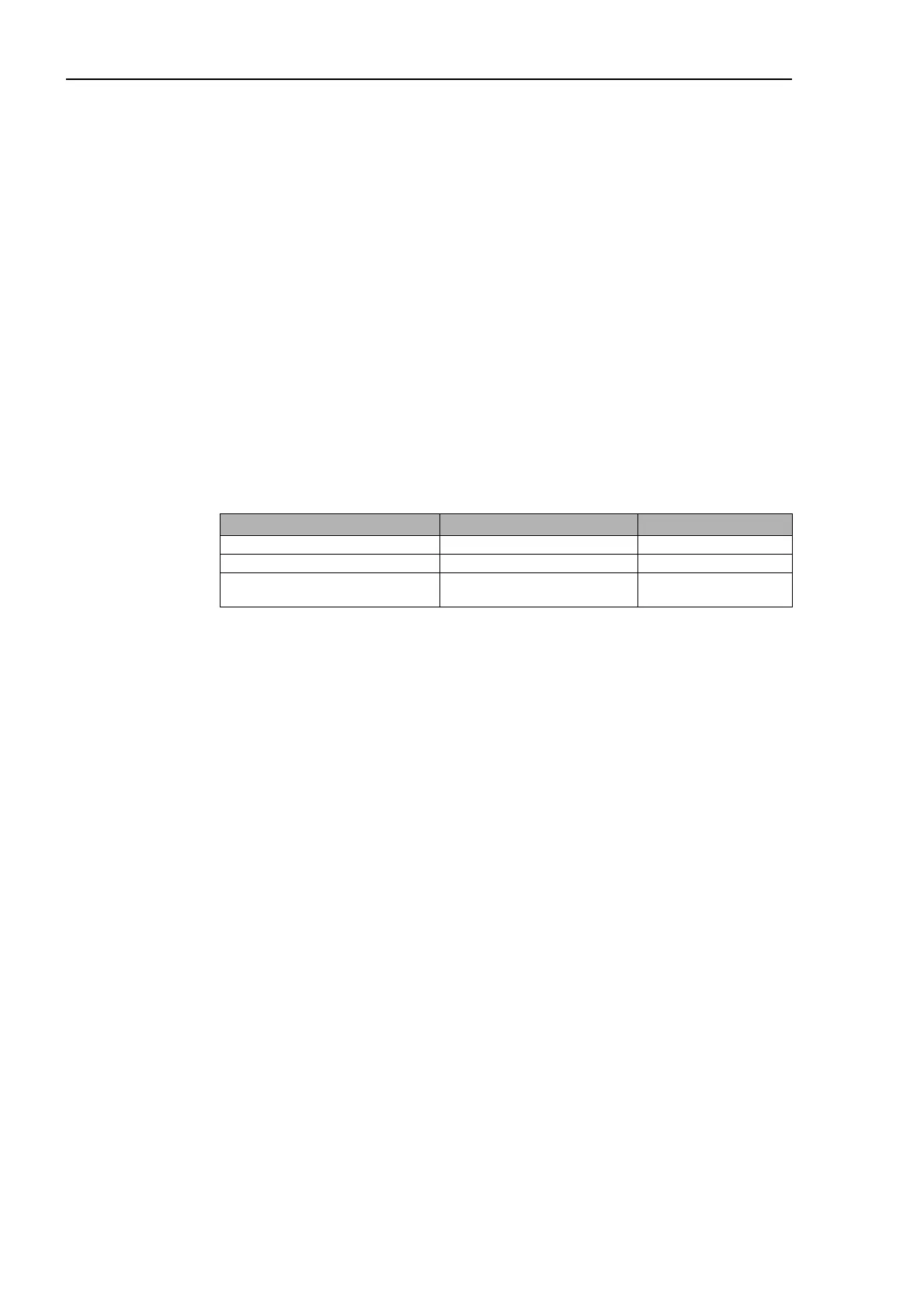
Operation:
Note on operation Key / parameter tree Parameter
Modulation P-band Xp (%/K) HEAT GENER. PARAMETER 19
Modulation sample time Ta HEAT GENER. PARAMETER 20
Modulation I-band Tn
(Reset time)
HEAT GENER. PARAMETER 21