EbV Product documentation THETA NORM/UNIT
13-3
13.3 Flow sensor VF
Types: VF 202 cable length 2 m
VF 204 cable length 4 m
Application: Contact sensor for mixer controlled heating circuits onto flow- or return pipes
Mounting location: Used as mixer flow sensor:
Behind the mixer pump for mixed heating circuit in the minimum distance of 50 cm.
In case of use as return flow sensors:
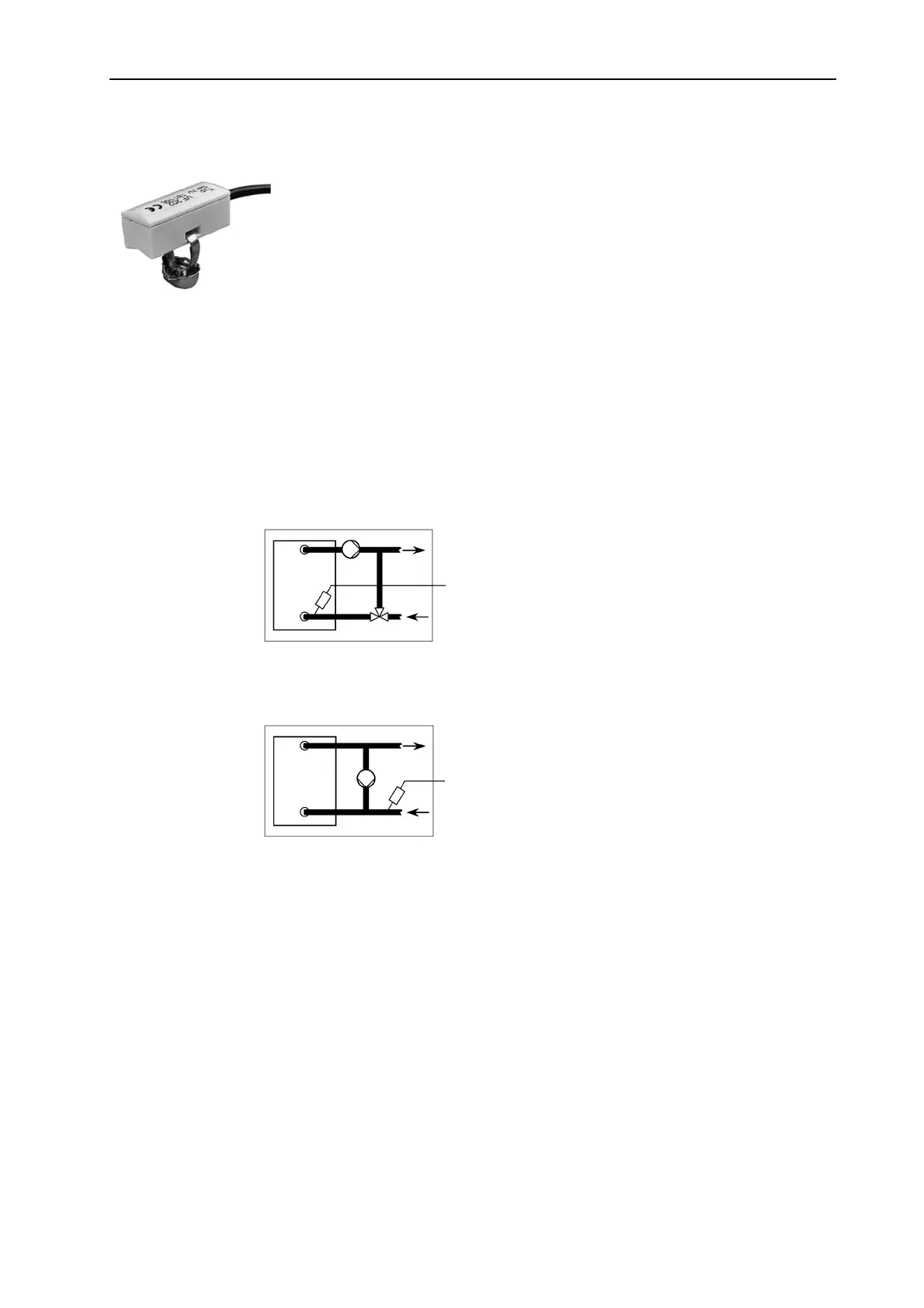
Controlled flow temperature addition by means of mixing valve
Bypass circuit by means of a bypass pump
Montage: - Clean flow pipe thoroughly and put thermal conduction paste to pipe surface.
- Attach sensor on the contact place in a flush way to the tube surface by means
of the enclosed clamping band.
- Pay attention to firm seat!
Electrical connection:
Connect sensors at the corresponding terminals of the respective control unit (see
terminal diagram). The terminals may be changed.
Feeding sensor VF
Return flow sensor
Return flow sensor