EbV Product documentation THETA NORM/UNIT
8-55
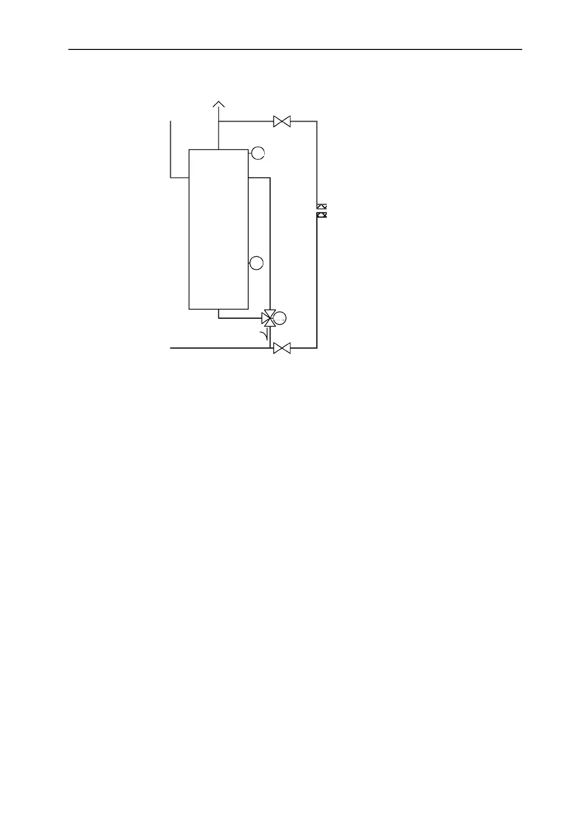
8.9 Hydraulic buffer release (HBR) (..VV..)
In buffer charging systems (buffer operating modes 1, 2 and 5), the buffer tank is charged by the H-GEN
without buffer release before the heating circuits can take up energy. First, the hydraulic buffer release
charges the top buffer area and the heating circuits are switched on. Then the HBR valve switches over so
that the whole buffer is loaded.
• If the output is unswitched, the buffer is loaded.
• If the output is switched, only part of the buffer is loaded (release active)
• The switching differential for switching the output is fixed at 5 K.
• At buffer setpoint + half of SD, the output switches off.
• At buffer setpoint - half of SD, the output switches on.
BU
SPBU
HBR
Buffer
tank