EbV Product documentation THETA NORM/UNIT
12-8
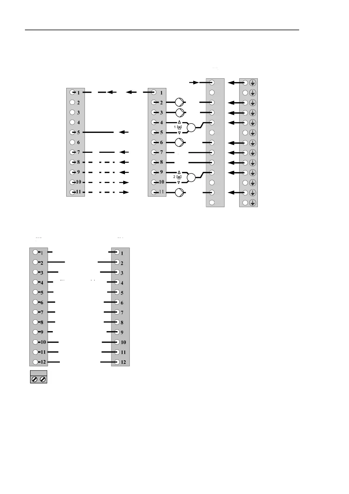
12.3.2 Electrical connection in wall socket MS-K
230 V~ Connections
Sensor and data bus connections Burner connections
T1 Control terminal stage 1
T2 Control terminal stage 1
B4 Op. hours counter burner stage 1
B5 Op. hours counter burner stage 2
T6 Control terminal stage 2
T7 Control terminal stage 2
T8 Control terminal stage 2
L1 Mains 230 V~ (live)
N Mains 230 V~ (neutre)
Pumps and actuators
HC-P Unmixed circuit pump
SOL-P DHW charging pump
MCP1 Pump for mixed heating circuit 1
MCP2 Pump for mixed heating circuit 2
1 K 5 actuator mix. valve 1 (OPEN)
1 K 3 actuator mix. valve 1 (CLOSED)
2 K 5 actuator mix. valve 2 (OPEN)
2 K 3 actuator mix. valve 2 (CLOSED)
L
Vo1
Variable output 1 (live)
L
Vo2
Variable output 2 (live)
X7
T1
T2
X8
N (mains)
X9
X10
HC-P
SOL-P
MC1-P
M
VO1
L
VO2
L
M
MC2-P
N
N
N
N
N
N
N
N
N
N
N
N
N
L1 (mains)
B4
B5
T6
T8
T7
X5
X6
B
-data bus-
A
Outdoor
Heat generator
Domestic hot water
Flow mixing circuit 1
Variable input 1
Variable input 2
Variable input 3
Flow mixing circuit 2
Solar panel flow
Solar tank
Pulse input
Boiler-Data bus