EasyManua.ls Logo

Rotex GW-30 C22 - Page 82

Rotex GW-30 C22
Print Icon
To Next Page IconTo Next Page
To Previous Page IconTo Previous Page
Loading...
29
5.10.3 Permitted pipe lengths at parallel air supply and flue tube systems
Permitted pipe lengths when applying Ø80 mm (total of flue pipe and air intake pipe
together).
C13
C33
C43
C53
C83
RKOMBG22AAV1
100 m
100 m
100 m
100 m
100 m
RKOMBG28AAV1
85 m
85 m
85 m
85 m
85 m
RKOMBG33AAV1
80 m
80 m
80 m
80 m
80 m
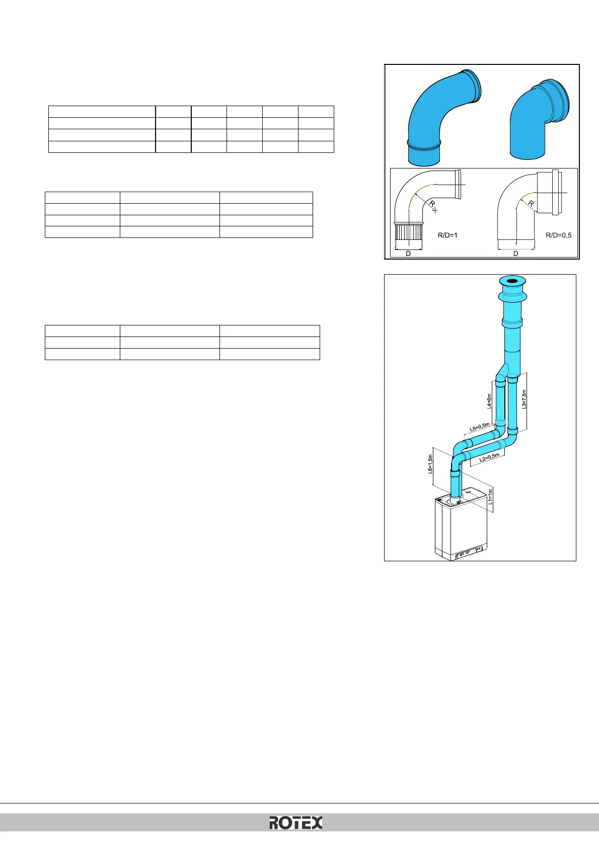
Replacement lengths
Bend 90°
R/D=1
2 m
Bend 45°
R/D=1
1 m
Knee 90°
R/D=0.5
4 m
Knee 45°
R/D=0.5
2 m
Calculation example
Pipe
Pipe lengths
Pipe length total
Flue gas outlet
L1 + L2 + L3 + 2x2 m
13 m
Air supply
L4 + L5 + L6 + 2x2m
12 m
Note:
The total pipe length is: sum of the straight pipe lengths + sum of the replacement pipe
lengths of bends/knees amounts to a total of 25 meters. If this value is less than the
maximum permitted pipe length, the flue gas outlet meets the requirements on this point.

Table of Contents