MCA-C3 Test Procedure
Page 55 of 77
Zone IR
1. Set the SRC2 to emit Sony TV Codes. Use TV code 11100.
Refer to the SRC2 owner’s manual to set device codes.
The IR Switcher PCB works as follows:
a) Each column of LED’s is a source
b) For Source 1 D12 corresponds to Sony button 1
For Source 1 D10 corresponds to Sony button 2 and so on.
Only numeric buttons 0-9 will illuminate an LED.
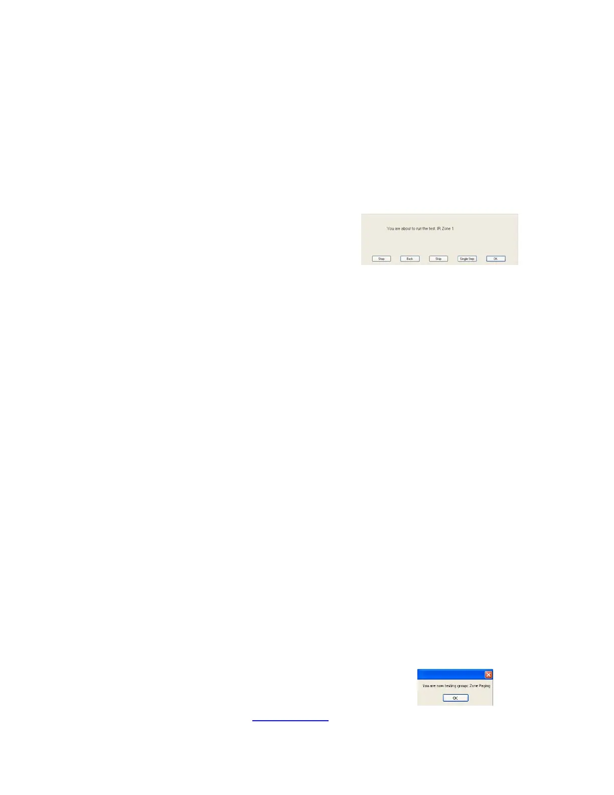
2. Press the space bar at the “IR Zone (x)” dialog.
Point the Remote control at the MDK-C5 keypad for Zone (x) tested.
Press TV button then press and hold the number 8 button on the SRC2.
D5, D157, and D168 illuminates. D157 and D168 are the Link LEDs.
Press and hold the number 8 button on the SRC2.
Do not release the number 8 button until this test is complete.
After 1.5 seconds the number 8 Led for Source 2 will illuminate.
The LEDs, D158 and D167, above the Source 2 column will illuminate also.
This will repeat as the test script switches to each source.
Source 7 D83 will illuminate continually while the other sources are switched.
Source 7 is connected to the COM (Common) IR Output of the MCA-C3.
The Sources 1-6 + 7 will repeat for each IR Zone (x).
For the test to pass you must view the following for the zone under test.
a) Only one Source LED and corresponding Link LED’s will illuminate for
approx 1 second of the 1.5 second between each source change.
b) Two source LED’s can’t be illuminated for 1.0 second between each
source change. Same thing applies to the Link LED’s.
c) Sources 1-6 plus Source 7 will repeat for each IR Zone (x)
then each IR Zone (x) will stop on Source 1.
d) Source 7 of the IR Switcher PCB will remain illuminated while you hold
the number 8 button of the remote. It is the common IR output of the
MCA-C3. Only the number 8 LED should be illuminated.
Release the number 8 button on the SRC2.
3. Repeat Step 2 for IR Zone (x), x = Zone 2 through 6.
4. Press the space bar to start the next group “Zone Paging”.
5. Continue by performing the “Zone Paging”
section.