108
Member of Exel group
DRT582165110
A - 2023/03
5.2. Installation
Note: The equipments are tested in air and water to check the correct operation and the tightness of all components.
For installation rules: see § 1.5.1 page 20
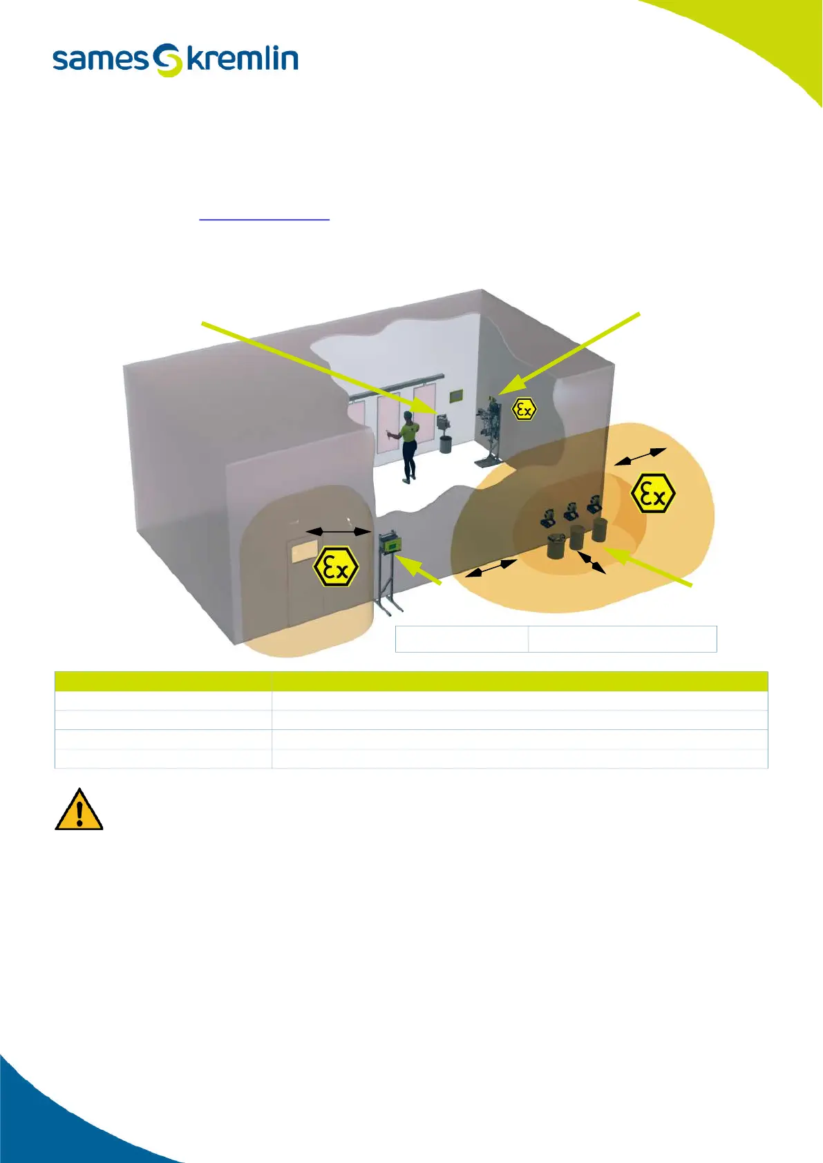
5.2.1. Configuration of the product part in and out of the cabin
The 1 m / 39.37’’ distance indicated in this diagram is given as for information purposes only and hold harmless to
Sames.
The exact delimitation of the zones is the express responsability of the user, depending on the materials used, the
environment and the conditions of use.
The 1 m / 39.37’’ distance can be modified if the analysis conducted by the user requires it.
(refer to standard EN 60079-10).
Item Description
1A Control panel
1B Product plate
2 Flush box
3 Pumps + Accessories
Inside
the cabin Area1
Outside the
cabin safe Area
B
A
Z2
Z2
Z1
1m
1m
1m
1m
A - Explosive Area 1 (Z1) or
Area 2 (Z2): paint booth
B - Non-explosive area
2
1A
1B
3