124
Member of Exel group
DRT582165110
A - 2023/03
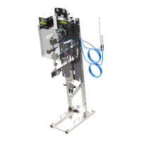
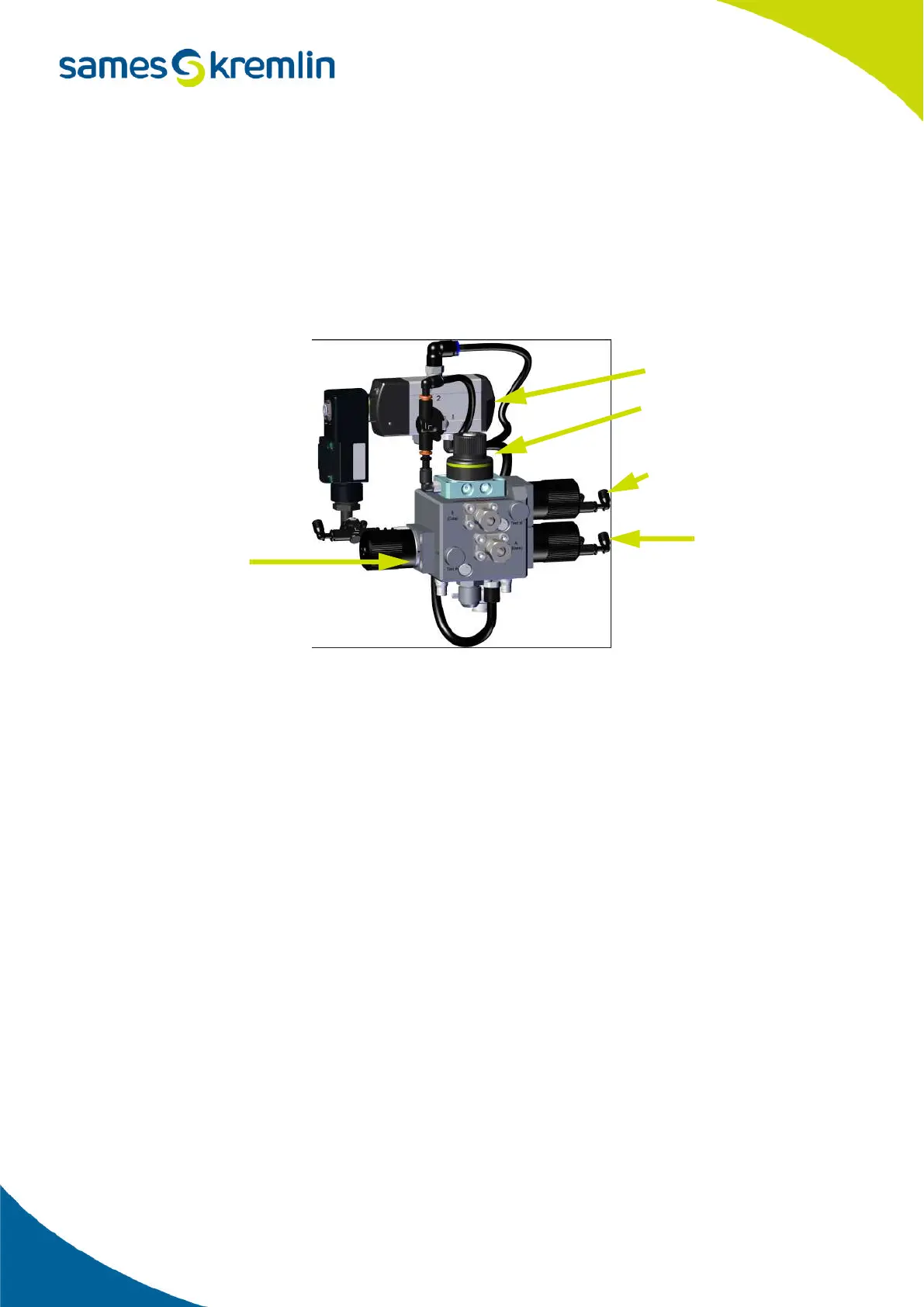
5.2.16. Connection of the mixing block
The 2K mixing block consists of 4 valves which are controlled from the main control panel.
The 4 valves are:
• The injection valve,
• The sampling valve on the catalyst side,
• The AIRCHOP valve,
• The sampling valve on the base side.
5.2.17. Injection valve connections
The injection valve is controlled via output 31 on the DIOB 1 card.
The injection valve is a pneumatic valve controlled by the solenoid valve located behind the protective cover.
It is therefore necessary to connect the solenoid valve electrically.
The cable is already connected on the solenoid side but it is necessary to connect it on the control panel side.
Connect the brown wire on the cable to terminal 1 (low terminal) of the 1226X1 terminal block.
Connect the blue wire to the 0V distribution terminal block at position 6 of the 6th terminal.
Solenoid injection valve
Injection valve
Sampling valve
AIRCHOP valve
Sampling valve
on the base side
on the catalyst side