5-6 EB 8331-4 EN
Installation
addition, the adjustment gears (18) must
engage properly in the corresponding
gears of the contact cam unit (21).
8. Secure the contact cam unit (21) and in
-
termediate gear (1) with the serrated ring
(3);pushdowntheserratedringasfaras
it will go.
9. Position the terminal board (17) at the
baseofthesupportata45°angle(ap
-
prox.) with the switches pointing towards
the gears. Swivel the upper end of the ter
-
minal board towards the gears until the
board is in a vertical position and proper
-
ly engaged in the support.
10. Adjust limit contacts as described in the
'Start-upandconguration'section.
11. Replacecover.Brieyturnthefastening
screws counterclockwise with a screw-
driver to center them. Then fasten down
the cover by tightening the screws.
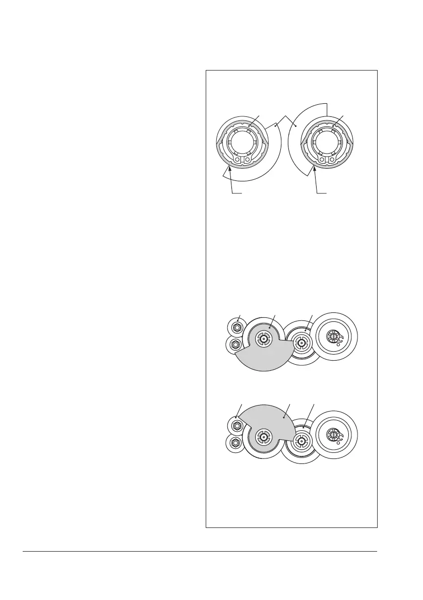
Actuator stem re-
tracted
Actuator stem
extended
19 1920
Fig.5-8: Alignment of contact cam and cam
holder
B
B
When actuator stem retracted
When actuator stem extended
Fig.5-9: Alignment of the contact cam unit