EB 5573-1 EN 75
Functions of the heating circuit
Parameters WE Parameters: value range
Flow temperature Point 1
Point 2
Point 3
Point 4
70.0°C
55.0°C
40.0°C
25.0°C
PA1, 2 > P05: –5.0 to 150.0°C
Reduced ow temperature Point 1
Point 2
Point 3
Point 4
60.0°C
40.0°C
20.0°C
20.0°C
PA1, 2 > P05: –5.0 to 150.0°C
Return ow temperature Points 1 to 4 65.0°C PA1, 2 > P05: 5.0 to 90.0°C
Min. ow temperature 20.0°C PA1, 2 > P06: –5.0 to 150.0°C
Max. ow temperature 90.0°C* PA1, 2 > P07: –5.0 to 150.0°C
* With CO1, 2 > F05 - 1 the following
applies: Max. ow temperature: –5.0 to 50.0°C (50.0°C)
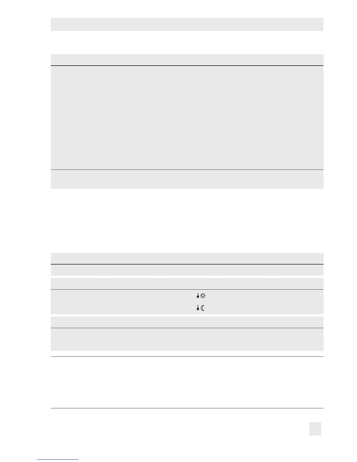
6.2 Fixed set point control
During the times-of-use, the ow temperature can be controlled according to a xed set
point. Outside the times-of-use, the controller regulates to a reduced ow temperature. Set
the desired rated ow temperature as 'Day set point', and the reduced ow temperature as
'Night set point'.
Functions WE Conguration
Outdoor sensor CO1 > F02 - 0
Parameters WE Switch position: value range
Day set point 50.0°C
: Min. to max. ow temperature
Night set point 30.0°C
: Min. to max. ow temperature
Parameters WE Parameters: value range
Min. ow temperature 20.0°C PA1, 2 > P06: –5.0 to 150.0°C
Max. ow temperature 90.0°C PA1, 2 > P07: –5.0 to 150.0°C
Note:
A xed set point control in heating circuit HC2 can only be congured with CO2 >
F02 - 0 when CO1 > F02 - 0 is also congured since heating circuit HC2 congured
with CO2 > F02 - 0 only uses the measured outdoor temperature provided by heat-
ing circuit HC1.