92 EB 5573-1 EN
Functions of the DHW circuit
Parameters WE Switch position: value range
Night set point for DHW temperature
40.0°C
: Min. to max. adjustable DHW set point
Min. adjustable DHW set point* 40.0°C PA4 > P01: 5.0 to 90.0°C
Max. adjustable DHW set point* 60.0°C PA4 > P02: 5.0 to 90.0°C
Hysteresis** 5.0°C PA4 > P03: 1.0 to 30.0°C
Charging temperature boost*** 10.0°C PA4 > P04: 0.0 to 50.0°C
Max. charging temperature 80.0°C PA4 > P05: 20.0 to 150.0°C (only with VF4)
Lag time for storage tank charging pump 1.0 PA4 > P06: 0.0 to 10.0
* Parameters serve as limitation of the adjustment range for the DHW temperature to be set at the rotary switch
** Deactivation value T = 'DHW temperature' + 'Hysteresis'
*** Charging temperature T = 'DHW temperature' + 'Charging temperature boost'
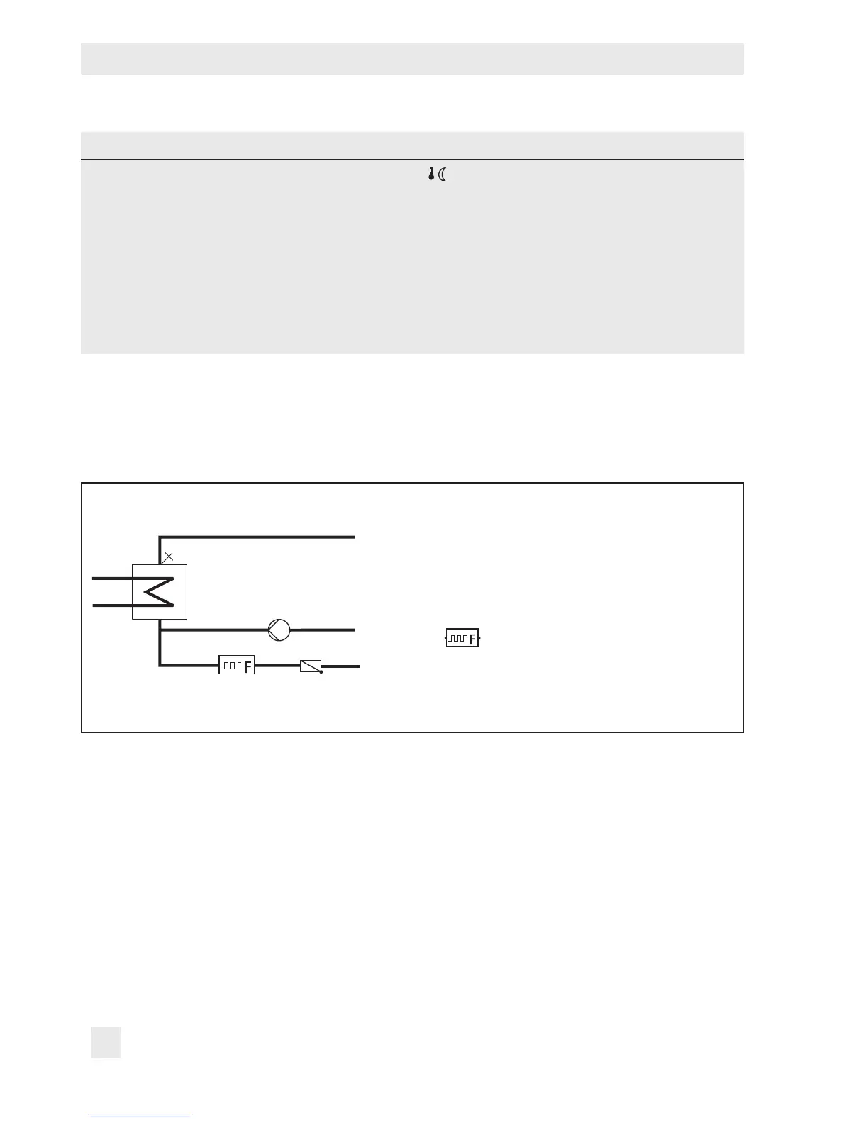
7.3 DHW heating in instantaneous heating system
Flow rate sensor
Fig. 9: Schematics of an instantaneous heating system
Without ow rate sensor or ow switch, the control of the required DHW temperature at the
ow sensor VF is only active during times-of-use of the circulation pump ZP. The ow rate
sensor or ow switch allows the controller to recognize when DHW tapping starts and stops.
Control of the required DHW temperature can made to be active only during DHW tapping
by deleting all times-of-use of the circulation pump.
The control of the required DHW temperature at the ow sensor VF is only active during
times-of-use of the circulation pump ZP.