EB 5573-1 EN 89
Functions of the DHW circuit
Parameters WE Parameters: value range
Charging temperature boost*** 10.0°C PA4 > P04: 1.0 to 50.0°C
Lag time for storage tank charging pump 1.0 PA4 > P06 x Valve transit time: 0.0 to 10.0
* Parameters serve as limitation of the adjustment range for the DHW temperature to be set at the rotary switch
** Deactivation value T = DHW temperature + 'Hysteresis'
*** Charging temperature T = DHW temperature + 'Charging temperature boost'
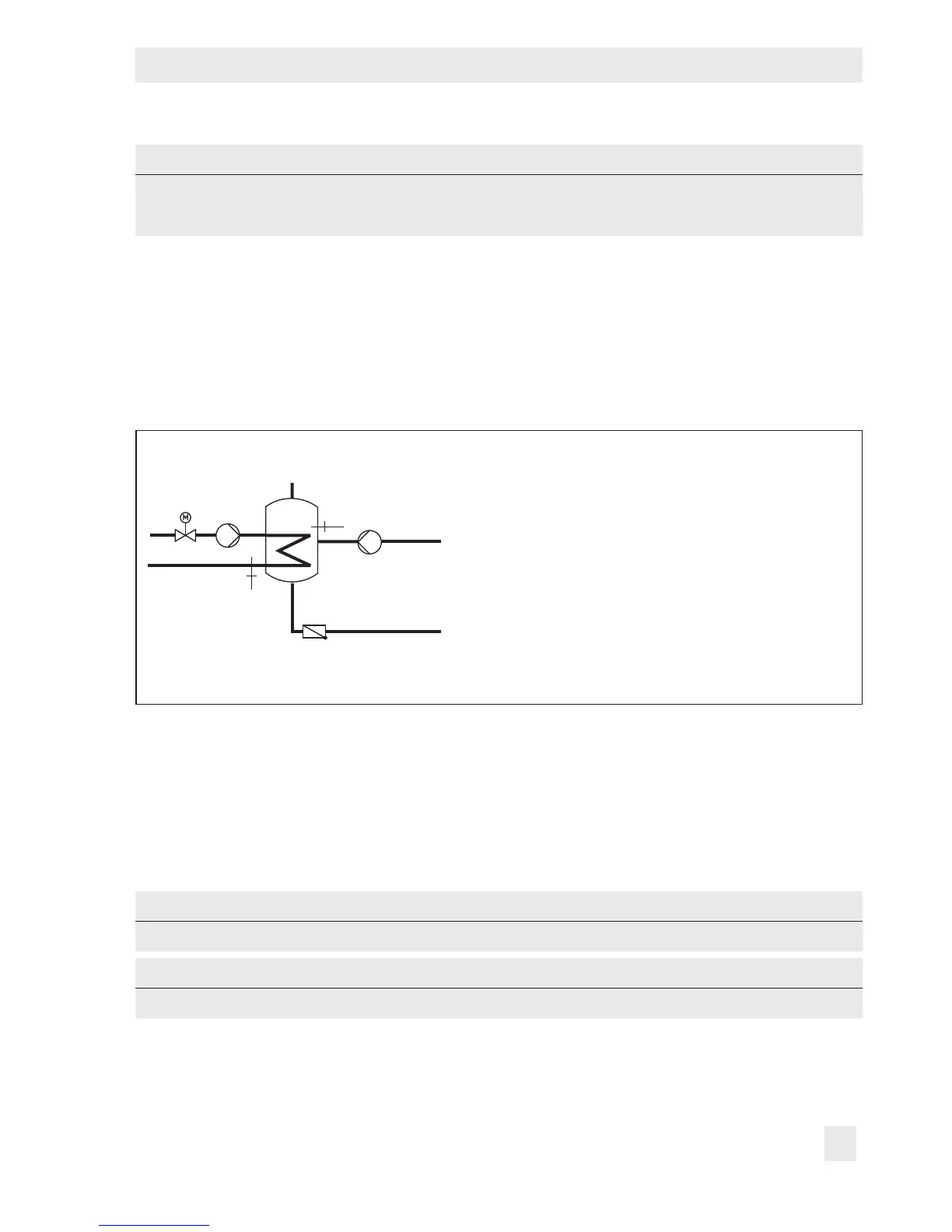
7.1.1 DHW circuit additionally controlled by a globe valve
In system Anl 11.1, the following version with globe valve can be congured instead of the
three-way valve control in the DHW circuit:
KW
SF1
VF2
ZP
SLP
Rk2/Y2
RK2/Y2 Control circuit/valve 2
SLP Storage tank charging pump
SF1 Storage tank sensor 1
VF2 Flow sensor 2
ZP Circulation pump (DHW)
WW Hot water
KW Cold water
Fig. 7: Schematics of a storage tank system with a globe valve for return ow temperature limitation
Globe valve and temperature sensor VF2 are used exclusively for return ow temperature
limitation in the schematics shown above. The pre-control circuit provides at least the same
ow temperature as in the standard schematic version which is calculated from 'DHW tem-
perature set point' + 'Charging temperature boost' + 'Boost set point (pre-control circuit)'.
The functions and parameters of the DHW heating in the storage tank system are upgraded
by the following settings:
Functions WE Conguration
Return ow control 0 CO4 > F20 - 1
Parameters WE Parameters: value range
Max. return ow temperature 65.0°C PA4 > P07: 20.0 to 90.0°C