MAINTENANCE
5-31SY95C Excavator OMM
Hydraulic System
Check the Accumulator Function
• The accumulator contains pressurized nitrogen.
Improper handling is extremely dangerous.
• Do not drill holes on the accumulator or place it
close to fire or a high-heat source.
• Do not weld any part on the accumulator.
• Air in the accumulator must be released upon
disposal.
• See “Accumulator” on page 2-6 for special
precautions that need to be taken when working
with or around the accumulator.
• Contact a SANY dealer for additional information.
Failure to follow these warnings could result in
death or serious injury.
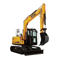
0003986
Figure 5-46
The pilot valve accumulator (1) allows the operator to
lower hydraulic functions within 15 minutes of an engine
shutdown with the key switch in the ON position.
1. Prepare the machine for checks and inspections.
See “Maintenance Safety” on page 2-5.
2. Lower the work equipment to 18 in.-24 in.
(0.45m-0.6m) from the ground.
3. Shut down the engine.
4. Turn the key switch ON.
0004483
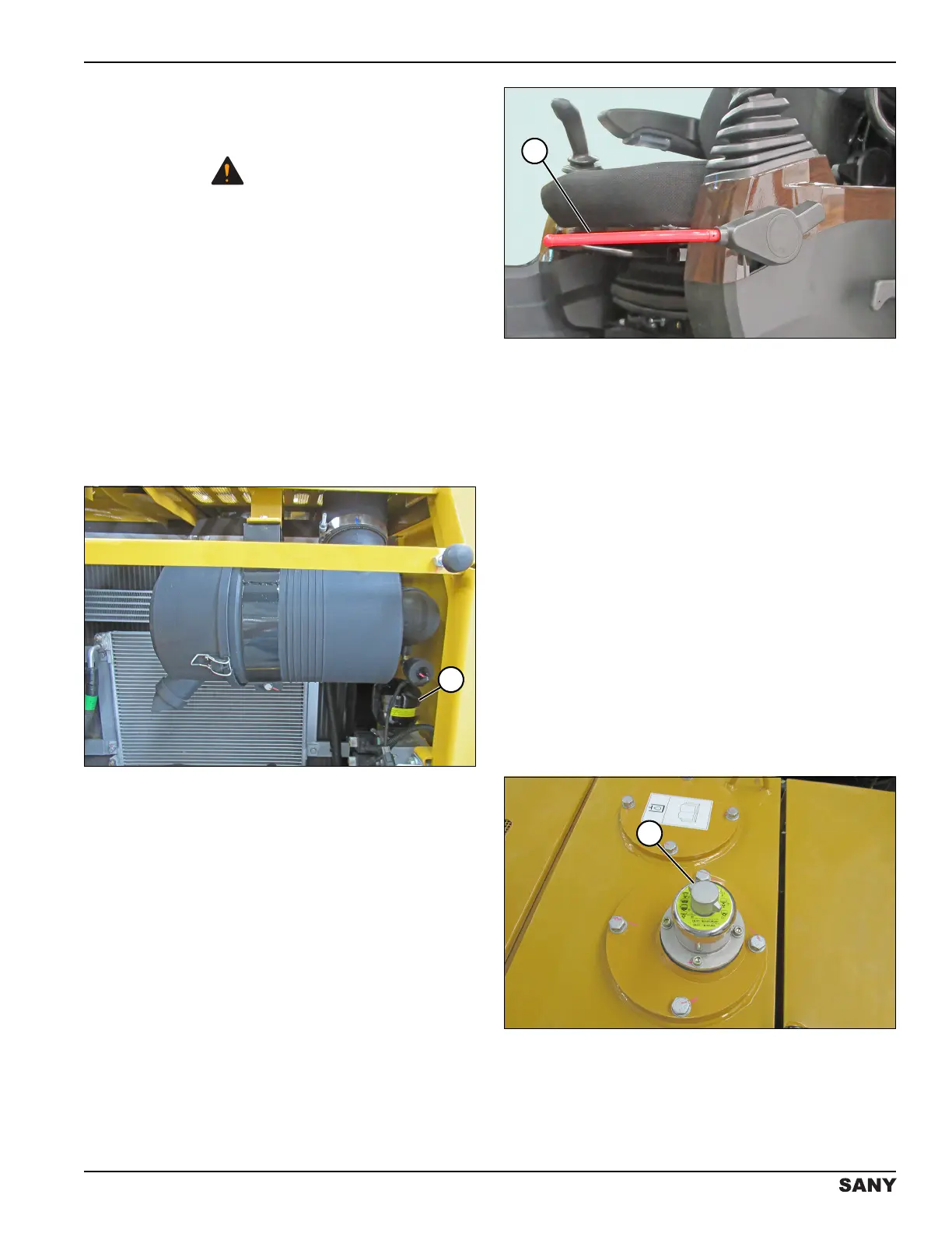
Figure 5-47
5. Move the hydraulic lockout control lever (1) to the
unlocked (open) position.
6. Use the joystick control to lower the boom.
7. The boom should lower.
NOTE: If there is no movement, contact a SANY dealer.
Relieve Hydraulic System Pressure
NOTE: Hydraulic system pressure must be relieved
before disconnecting or servicing hydraulic
system components.
1. Prepare the machine for service. See “Maintenance
Safety” on page 2-5.
2. Turn the key switch to ON. Do not start the engine.
3. Set the hydraulic lockout control lever to the
unlocked (open) position.
4. Fully cycle each pedal, joystick, and travel control
two to three times to release the system pressure
remaining in the hydraulic lines.
5. Turn the key switch to OFF.
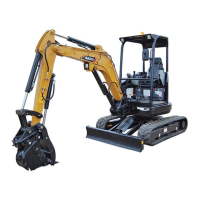
0004458
Figure 5-48
6. Remove the wing nut cover (1).