MACHINE CONTROLS
3-25SY95C Excavator OMM
Pattern Change (SAE/BHL) Valve
Shut down the engine before adjusting the pattern
change (SAE/BHL) valve.
Failure to follow this notice could damage the
environment, the machine, or cause the machine
to operate improperly.
0004475
Figure 3-47
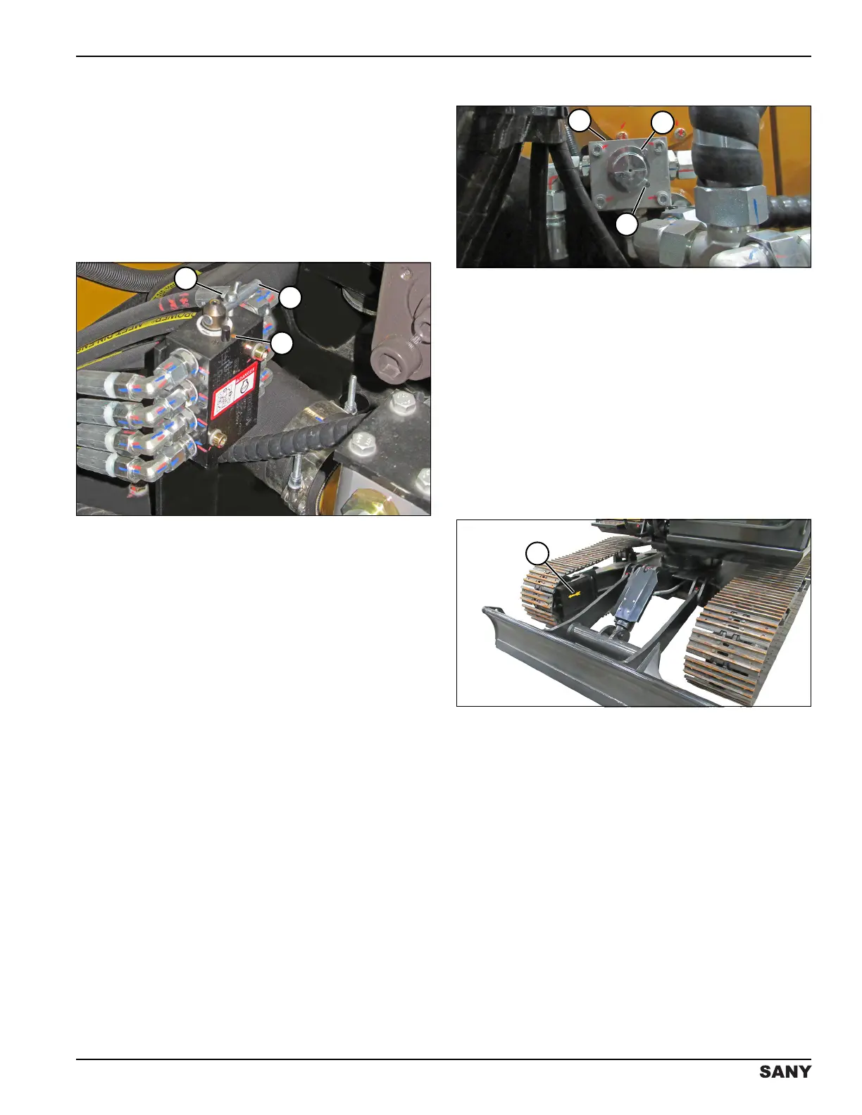
The pattern change (SAE/BHL) valve changes control of
the boom and arm from one joystick to the other. It is
located behind the left rear access door. Position the
SAE/BHL pattern card (not shown) in the right cab
window holder to match the current position. The SAE
pattern is on one side of the card, and the BHL pattern is
on the other side.
To change the operation mode, perform the following
steps:
1. Turn the engine off. See “Engine Shutdown” on
page 4-16.
2. Open the left rear access door. See “Left Rear
Access Door” on page 5-15.
3. Loosen the wing nut (1).
4. Rotate the bar (2) to the operator-preferred mode
position.
5. Tighten the wing nut into the threaded hole (3) to
secure.
6. Close and secure the left rear access door.
Return Flow Selector Valve
0004479
Figure 3-48
The return flow selector valve (1) has a one-way (3) or
two-way (2) position (shown) for operating optional
equipment. It is on the side of the fuel tank.
A variety of optional one-way and two-way flow
equipment is available for use on this machine. A
hydraulic breaker is an example of one-way flow
equipment; a tilt bucket is an example of two-way flow
equipment.
NOTE: Check the work tool operator manual for hydraulic
flow rate information.
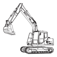
Direction Arrow
0004491
Figure 3-49
The direction arrow (1) on each of the track frames
indicates forward movement of the machine. Check
these arrows before using the travel control
levers/pedals. The drive sprocket is at the rear of the
track frame.
If the track frame is facing backward, the travel direction
will be opposite the maneuvering direction of the travel
control lever/pedal. The machine will move forward when
you pull the control levers backward, and backward when
you push them forward. Left and right control directions
are also reversed when the track frame faces backward.