-44-
Electrical Adjustment
v
Component-Auto calibration
Input mode Video mode (Component)
Input signal 100% color bar signal (480i)
100% color bar signal (480p)
100% color bar signal (720p)
100% color bar signal (1080i)
1. Enter the service mode.
2. To start the auto-calibration for component-video
adjustment, select Group "260", No. "0", and then
change data value "0" to "1".
After the auto-calibration completed, "OK" will appear
on the screen.
3. Take auto-calibration for each component signal listed
above.
PC, Video, Component Manual adjustment
When the PC, Video or Component Auto Calibration
fails, take the following manual adjustment instead of
auto calibration.
[1] PC Manual adjustment
Input mode Computer mode
Input signal 16-step gray scale computer signal
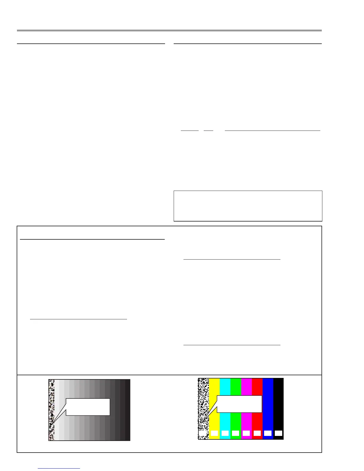
Adjust the data values as the 100% white part on the
screen becomes the most noisy (darkest).
Group No. Adjustment
10 - 3 ADC-Green Gain
10 - 4 ADC-Red Gain
10 - 5 ADC-Blue Gain
[2] Video Manual adjustment
Input mode Video mode (Composite)
Input signal 100% color bar signal
Adjust the data values as the 100% white part on the
screen becomes the most noisy (darkest).
Group No. Adjustment
20 - 0 Y Level
[3] Component Manual adjustment
Input mode Video mode (Component)
Input signal 100% color bar signal (480i)
100% color bar signal (480p)
100% color bar signal (720p)
100% color bar signal (1080i)
Adjust the data values as the 100% white part on the
screen becomes the most noisy (darkest).
Group No. Adjustment
0 - 3 ADC-Green Gain
0 - 4 ADC-Red Gain
0 - 5 ADC-Blue Gain
b Common Voltage adjustment
Input mode Computer mode
Input signal 50%-RGB pattern computer signals
or 16-step gray scale computer sig-
nal
Advanced Color
Off
1. Enter the service mode.
2. Select Group "101", No. "1" and then change data val-
ue from "2" to "0" to reduce the panel frequency.
3. Change data value to obtain the minimum flicker for
each color on screen.
Group No. Adjustment
100 - 11 for red flicker
100 - 9 for green flicker
100 - 10 for blue flicker
4. Select Group "101", No. "1" and then change data val-
ue from "0" to "2".
Black and noisy
image appears
To switch Advanced Color function "Auto" or "Off"
Display on-screen menu, and select "Image" -> "Ad-
vanced Color" -> "Auto" or "Off".
Black and noisy
image appears
16-step gray scale 100% full color bar

 Loading...