Chapter 3 Functional descriptions
SMSO-2-02.03- 15.07.03 63
Transistors as switching circuit
Electronics switching circuits are installed in a wide variety of devices. However, their physical and electronic characteristics
differ considerably from the conventional electronics switching circuits with mechanical switching elements. Thus, a little knowl-
edge is required in order to carry out an appropriate troubleshooting and fault rectification to electronic switching circuits. So,
everyone who carries out test and maintenance work to electrical and electronic circuits must know the specific properties of
such circuits, and above all, be able to tell the difference between these two circuit types.
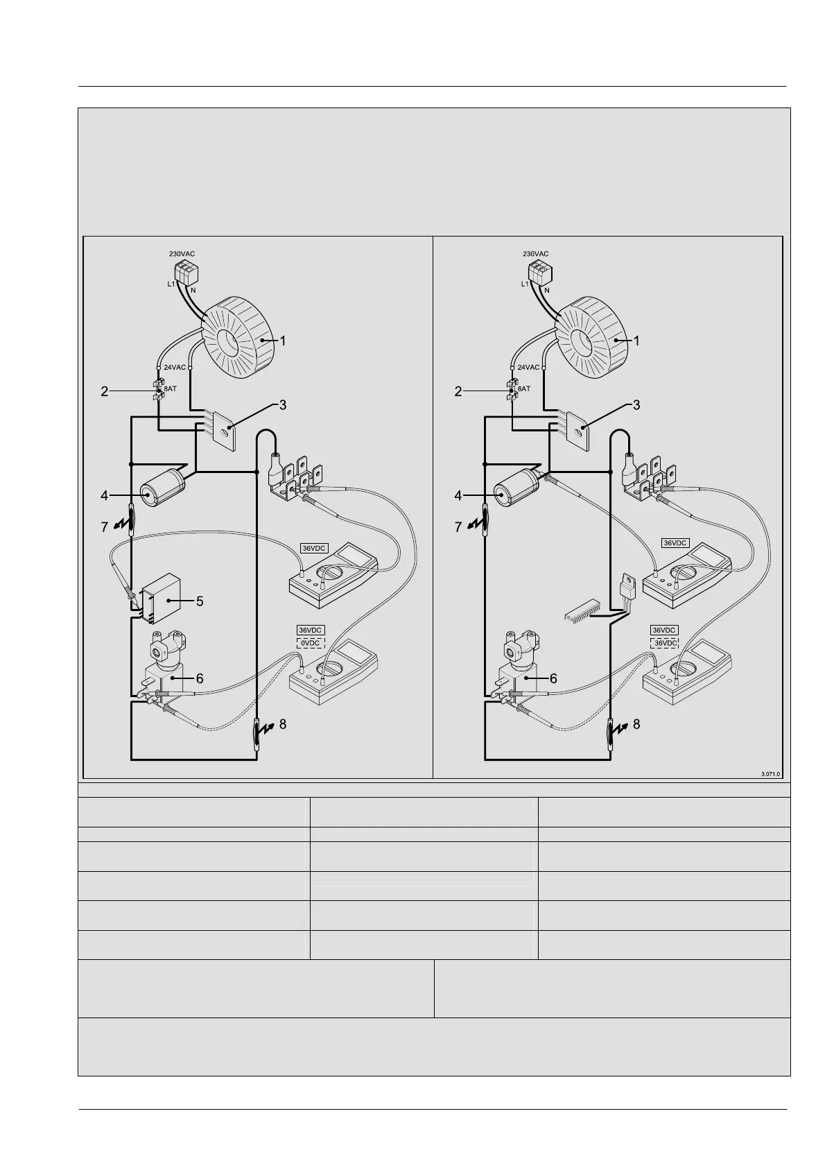
The most important differences are shown below in the example of a valve actuation system. The procedures inside the transis-
tor itself (actuation etc.) are not important to such understanding.
Peculiarities of the types of control system
Electrical control
(relay control)
Electronic control
(Power transistor in emitter circuit)
Switch in high potential
Configuration of switching elements
Switch in low potential
no voltage at consumer (=coil) in zero-
current status
Consumer terminals
(Valve)
Voltage of 36V at both consumer terminals
at zero-current status.
negative pole (=GND) is on one consu-
mer terminal
Negative pole
Negative pole is on housing and at transistor
collector.
Earth contact at + causes fuse to react
Fault
Earth contact at +
Earth contact at + causes fuse to react
Earth contact at – does not cause a
critical condition.
Fault
Earth contact at -
Earth contact at – causes consumer to
switch on automatically
1 Toroidal core transformer
2 Device fuse
3 Rectifier
4 Electrolytic capacitor to smooth out DC voltage
5 Power relay
6 Solenoid valve
7 Earth contact in high potential
8 Earth contact in low potential = fault
The unusual point about the emitter circuit is that the negative pole is switched with the switching element (=power transistor).
Thus it follows that the control voltage for all consumers such as valve coils etc in “zero-current” (=not switched on) status, is at
+36V DC. When they are “switched on” the transistor switches the negative pole (=low potential) and only thus does the con-
sumer activate.