Safety and Functional Tester GLP2-i/e
During the test, test object and test leads must not be touched!
The safety measures required by law must be adhered to!
Schleich GmbH * D-58675 Hemer * 0049 / (0)2372 / 9498-0 * 0049 / (0)2372 / 9498-99 *
http://www.schleich.com * info@schleich.com 72
Information on the detection of the measurable resistances and the supply lead
In principle, the PE test raises the question, which resistances are measurable at which current level in
dependence on the no-load voltage and the cable length to the test probe.
This question cannot be answered in general terms. For this reason, it is necessary to clarify the technical
boundary conditions, before the max. measurable resistance can be detected. After this, it is necessary to
do a calculation with the help of two equations.
The following technical conditions need to be clarified:
1. maximum PE test current?
2. maximum no-load voltage?
3. highest resistance to be measured at the test object?
4. maximum cable lengths between tester and test object?
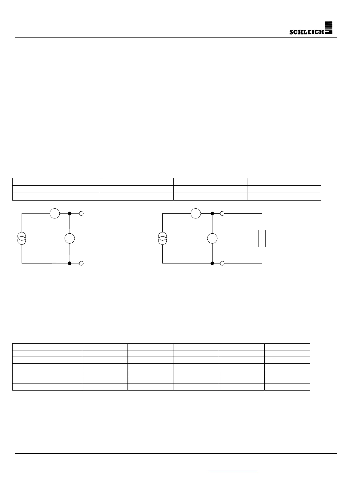
On the basis of Ohm’s law, first the maximum measurable resistance is determined. In dependence on the
no-load voltage and the PE test current, the below table shows the resistances.
Ohm’s law for calculating the resistances is: R=U/I
Table1 PE test current = 10A PE test current = 25A PE test current = 30A
No-load voltage = 6V R
max
= 0.6ø R
max
= 0.24ø R
max
= 0.2ø
No-load voltage = 12V R
max
= 1.2ø R
max
= 0.48ø R
max
= 0.4ø
R
PE
AA
V V
Stromquelle StromquelleU
Leer
U
PE
I
PE
I
PE
PE test in no-load operation (U
leer
=6V or 12V) PE test (U
PE
=R
PE
*I
PE
)
Stromquelle = current source
As you can see from the table, only resistances up to certain maximum values can be detected at the PE
test. These maximum values are pure theoretical values, because under practical conditions, the resistances
in the leads must be considered additionally.
These resistances depend on the length of the lead and the cross-section of the lead.
The equation for calculating the resistance of a lead is: R=L/(56*A)
L is the length of the lead and A is the cross-section of the lead.
The table below shows some example results in dependence on length and cross-section.
Table2 Length = 1m Length = 2m Length = 5m Length = 10m Length = 20m
Cross-section = 0.75
2
mm
R
max
= 0.024ø R
max
= 0.048ø R
max
= 0.12ø R
max
= 0.24ø R
max
= 0.48ø
Cross-section = 1.5
2
mm
R
max
= 0.012ø R
max
= 0.024ø R
max
= 0.06ø R
max
= 0.12ø R
max
= 0.24ø
Cross-section = 2.5
2
mm
R
max
= 0.007ø R
max
= 0.014ø R
max
= 0.036ø R
max
= 0.07ø R
max
= 0.14ø
Cross-section = 4
2
mm
R
max
= 0.004ø R
max
= 0.009ø R
max
= 0.022ø R
max
= 0.045ø R
max
= 0.089ø
Cross-section = 5
2
mm
R
max
= 0.003ø R
max
= 0.007ø R
max
= 0.018ø R
max
= 0.035ø R
max
= 0.07ø
Cross-section = 6
2
mm
R
max
= 0.003ø R
max
= 0.006ø R
max
= 0.015ø R
max
= 0.03ø R
max
= 0.06ø
When calculating the length of the lead, it must be taken into consideration that both, the lead to the PE
test probe and the lead to the opposite side of the PE resistance need to be comprised to the total
resistance. Therefore, both lengths need to be added (total length).