Safety and Functional Tester GLP2-i/e
During the test, test object and test leads must not be touched!
The safety measures required by law must be adhered to!
Schleich GmbH * D-58675 Hemer * 0049 / (0)2372 / 9498-0 * 0049 / (0)2372 / 9498-99 *
http://www.schleich.com * info@schleich.com 73
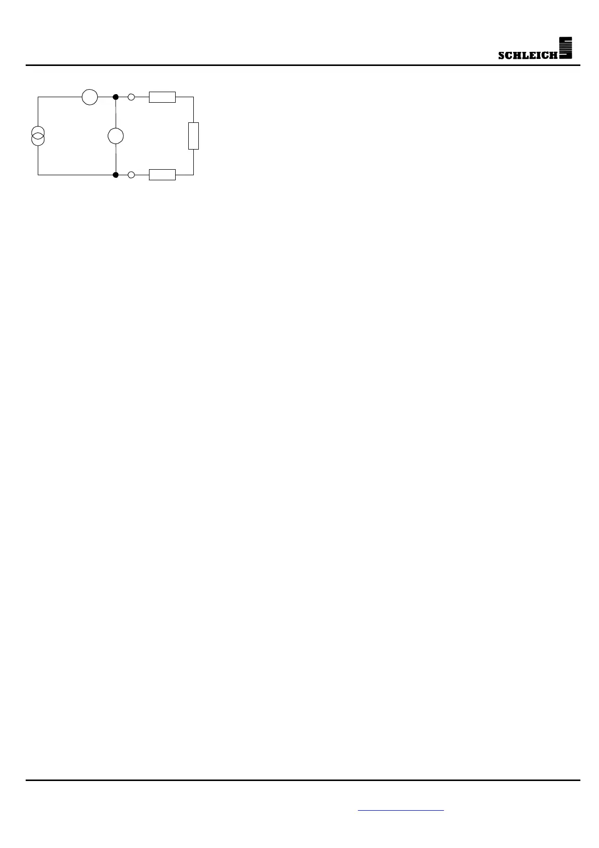
R
PE
A
V
Stromquelle U
Last
I
PE
R
Zu1
R
Zu2
Rgesamt=Rzu1+Rzu2 bzw. Lgesamt =Lzu1+Lzu2
The table shows clearly that, given a lead cross-section of e.g. 0.75
2
mm and a lead length of 20m, the
relatively large resistance of 0.48ø is formed.
This resistance together with the PE resistance to be tested, makes the maximum measurable total
resistance (please refer to table 1).
Example:
A no-load voltage of 6V and a maximum current of 10A results in a max. measurable resistance of
0.6ø (please refer to table 1).
If you now take, for example, a lead of 20m with a cross-section of e.g. 1.5
2
mm, the result is that
the max. measurable PE resistance is only 0.12ø, because: 0.6ø - 0.48ø = 0.12ø. (Please refer to
table 2)
If, however, the resistance to be measured at the test object has to be at least 0.2ø, you can only
increase the cross-section of the lead or shorten the lead. If this wasn’t done, the resistance would
still be measurable, the test current would, however, be reduced. This would not correspond to the
rule, though [I= 6V / (0.48ø+0.2ø) = 8.8A].
If the cross-section of the lead was increased to 1.5
2
mm, you would have the conditions below:
R at 20m = 0.24ø (see table 2)
R
PEmax
= 0.6ø - 0.24ø = 0.36ø
This means that PE resistances up to 0.36ø would be measurable. Only resistances starting at
0.36ø would lead to a reduction of the PE test current below 10A.