C.2
SEL-2701 Ethernet Processor Instruction Manual Date Code 20020501
GOMSFE Model Example
Settings
Settings
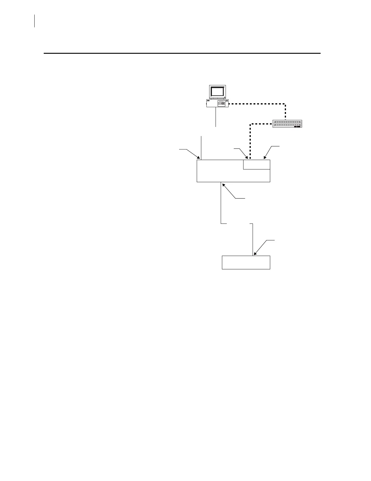
In this example, the SEL-351S Relay is connected to Port 5 of the SEL-2030
with a C273A cable as shown in Figure C.1.
Figure C.1 Example SEL-2030/SEL-351S Relay System.
The steps below configure the SEL-2030 to collect data from the relay and
configure the SEL-2701 in Card Slot 1 (Port 17) for UCA2:
Step 1. Connect the cables as shown in Figure C.1.
Step 2. Apply power to the relay, SEL-2030, and PC.
Step 3. Start a serial port terminal application on the PC and connect to
the SEL-2030.
Step 4. Log in to the SEL-2030 at Access Level 2.
Step 5. Configure the SEL-2030 serial port connected to the SEL-351S
Relay with the SET P 4 command. Change the Device Type
selection to S for SEL. Start an Autoconfiguration when
prompted and accept the remaining port settings.
Step 6. Configure the SEL-2030 automatic messaging to collect data
from the SEL-351S Relay with the SET A 4 command. Set the
automatic messaging settings as shown in Table C.1 on
page C.3. The 20METER and 20TARGET “20” messages
collect analog measurement and status data. The 20HISTORY
“20” message collects relay event history records.
SEL-2701
Hub
Front Port
Network
Port A
Port 17
Port 4
Port 3
SEL-351S Relay
SEL-2030
Communications Processor
C234A
C273A