SEL-3031 Instruction Manual Date Code 20181001
Installation
Overview
2.2
Radio Path
Spread-spectrum radios operating in the 900-MHz ISM band are limited by line-of-
sight. Radio line-of-sight is longer than optical line-of-sight because of the bending of
the radio wave toward the surface of the earth. This radio horizon is typically 30
percent longer than the visual horizon. The longer the communications path, the taller
the antennas must be to maintain the line-of-sight.
Obstructions in the line-of-sight will impact the performance of the radio, as the
strongest radio signal is communicated directly along the radio line-of-sight.
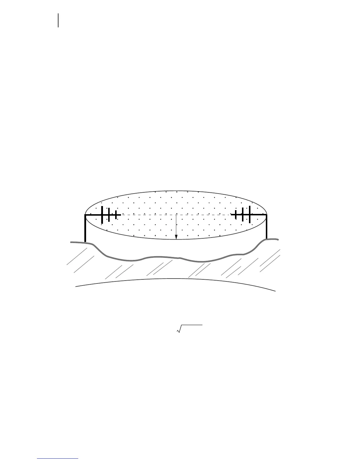
The line-of-sight between two antennas is shaped like an ellipse (called the Fresnel
zone). The point exactly halfway between the two antennas is the widest part of the
ellipse, as shown in Figure 2.1. At 900 MHz and 304.8 m (1000 ft) apart, the Fresnel
zone is 4.9 m (16 ft) in diameter. At 32 km (20 mi) apart, it is 51.8 m (170 ft) in
diameter. Anything within the Fresnel zone will obstruct and reduce signal strength and
availability (the ground, buildings, vegetation, etc.). Table 2.1 depicts the maximum
Fresnel zone diameter and path loss for some typical path distances.
Figure 2.1 Fresnel Zone
The formula used to calculate the widest distance of the Fresnel zone is as follows:
where:
b = radius of the Fresnel zone in meters
d = distance between transmitter and receiver in kilometers
f = frequency transmitted in GHz
d
b