SEL-3031 Instruction Manual Date Code 20181001
Installation
Communications
2.16
Communications
Serial Ports
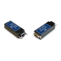
Table 2.10 shows the physical interfaces of the SEL-3031. Several options are provided
for Port 1 physical interfaces, including EIA-232, EIA-485, and fiber.
Serial (EIA-232 and EIA-485)
Use the EIA-232 port for communications distances of d15.2 m (50 ft) in low-noise
environments. Use the optional EIA-485 Port 1 for communications of d 1200 m
(3937 ft) maximum distance (to achieve this performance, ensure proper line
termination at the receiver).
If Port 1 is an EIA-485 connection, there are two types of connections that will work on
multidrop systems. Table 2.11 shows the standard pinout of a recommended four-wire
EIA-485 connection. If your system only works on a two-wire EIA-485 connection,
then you will need to connect Pins 1 and 7 together and Pins 2 and 8 together.
Figure 2.6 shows how to wire this configuration.
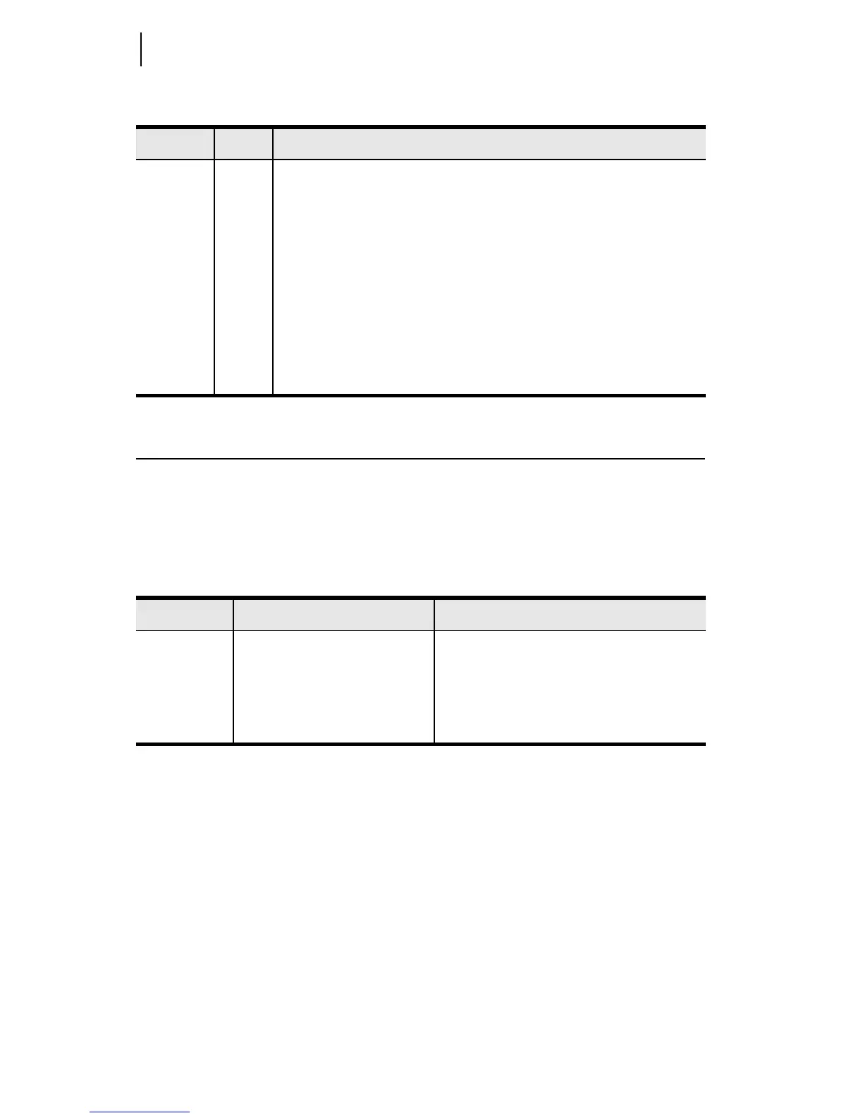
Table 2.9 Front-Panel Status Indicator LEDs
Label Color Description
ENABLE Green All self-tests are passing and unit is operational
ALARM Red ON: Self-test failure detected
Flashing: Antenna failure
SEC Green ON: Encryption card detected and wireless data secured
Flashing: Encryption card detected and in RESET
OFF: No encryption card present or card failed
LINK Green Communications link established between master and remote radio
TX 1, 2, 3 Green Serial data received by the port and transmitted out of the radio
RX 1, 2, 3 Red Radio data received and transmitting out of serial port
Table 2.10 SEL-3031 Port Description
Port Communications Interface Location
Port 1 EIA-232, EIA-485, or fiber Rear (Port 1 has three ordering options)
Port 2 EIA-232 Rear
Port 3 EIA-232 Rear
USB USB 1.1 Front (management port)